12
D10-991-2400B
D/G-10 Service (Fluid End)
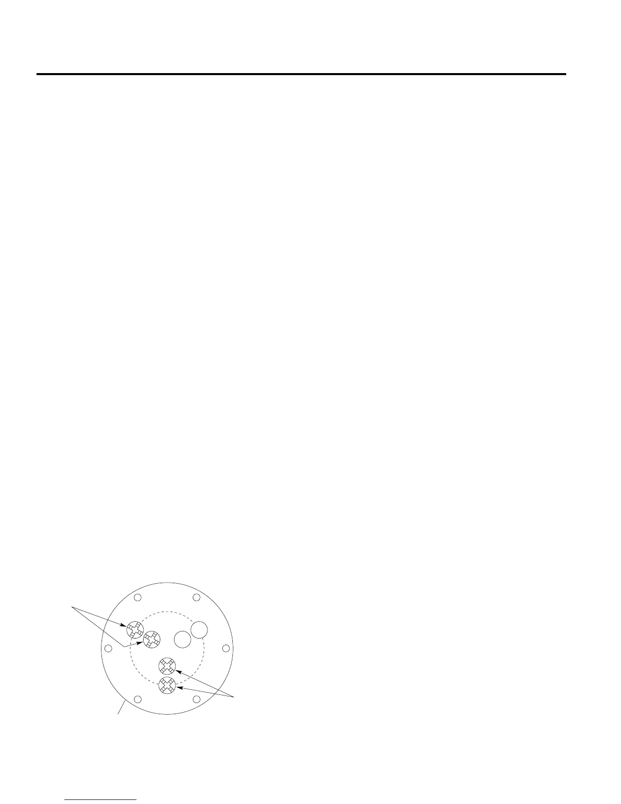
INCORRECT:
Retainer legs
pointing toward
center of pump.
Valve Retainer Orientation
In Valve Plate
W0237A
Valve plate (16)
CORRECT:
Retainer legs
45 degrees
off-center
of pump.
2. Inspect Valves (10-15, 39)
*NOTE: For non-metallic slurry duty pumps, see the insert
to this manual for fluid valve service (Step 2), then proceed
to Step 3 in this manual for remaining service steps.
The three inlet and three outlet valve assemblies are identical
(but face in opposite directions). Inspect each valve as
follows:
a. Check spring retainer (15), and replace if worn.
Note: if your pump has either abrasive duty valve
assemblies or a non-metallic pump head there will be
a plastic dampening washer (39) at the bottom of each
seat. Inspect each one for wear or cracks and replace
if necessary.
b. Check valve spring (13). If it is shorter than new spring,
replace it (don’t just stretch old spring).
c. Check valve poppet (12). If worn excessively, replace it.
NOTE: If your pump has plastic spring retainers, there
is a tetra seal (flat O-ring, 14) between the retainer (15)
and valve seat (11).
d. Remove valve seat (11). Seat remover is included in Wanner
Tool Kit. Inspect valve seat for wear, and replace it if
necessary.
e. Reinstall valve assemblies:
• Clean valve ports and shoulders with emery cloth, and
lubricate them with lubricating gel or petroleum jelly.
• Install O-ring (10) on valve seat (11).
• Inlet (3 center valves). Inser t spring retainer (15) into
valve plate, then insert spring (13), valve (12), and
valve seat (11). If pump has plastic spring retainers,
flat O-ring (14) goes between retainer and seat.
Insert dampening washer (39) if included in valve
assembly.
• Outlet (3 outer valves). Insert dampening washer (39)
if included in valve assembly. Insert valve seat, valve,
and spring, then retainer. If pump has plastic retainers,
install flat O-ring between retainer and seat. If pump has
metal spring retainers in outlet valves, position them
so leg does not point toward center of pump (refer to
illustration below).
3. Inspect and Replace
Diaphragms (20)
If necessary to ser vice the diaphragms, remove the two socket-
head cap screws (41) that secure the valve plate (16) to the
cylinder casting (24). Inspect the valve plate in the same manner
as you did the manifold.
a. Lift diaphragm by one edge, and turn pump shaft until
diaphragm pulls up. This will expose machined cross-holes
in plunger shaft behind diaphragm.
b. Insert Allen wrench through one of holes, to hold diaphragm
up. Proper size tool is included in Wanner Tool Kit.
c. Remove screw (17), O-ring (18), and follower (19) in center
of diaphragm.
d. Remove diaphragm, and inspect it carefully. Ruptured
diaphragm generally indicates pumping system problem,
and replacing only diaphragm will not solve larger problem.
Inspect diaphragm for following:
• Half-moon marks. Usually caused by cavitation of pump
(refer to “Troubleshooting” section).
• Concentric circular marks. Usually caused by cavitation
of pump (refer to “Troubleshooting” section).
• Small puncture. Usually caused by sharp foreign object
in fluid, or by ice particle.
• Diaphragm pulled away from center screw or from
cylinder sides. Usually caused by fluid being frozen in
pump, or by over pressurization of pump.
• Diaphragm becoming stiff and losing flexibility. Usually
caused by pumping fluid that is incompatible with
diaphragm material.
• Slice in ridge of diaphragm. Occurs when Viton
diaphragm is operated at cold temperatures.
• Diaphragm edge chewed away. Usually caused by over
pressurizing system.
e. Inspect plunger (21) for any rough surfaces or edges. Do
not remove plunger from plunger shaft. Smooth surfaces
and edges as necessary with emery cloth or fine file.
CAUTION: If a diaphragm has ruptured and foreign
material or water has entered the oil reservoir, do not
operate the pump. Check all diaphragms, then flush the
reservoir completely (as outlined below) and refill it with
fresh oil. Never let the pump stand with foreign material
or water in the reservoir, or with the reservoir empty.
f. Install new diaphragm (or reinstall old one, as appropriate),
ridge side out.
g. Clean screw (17) and remove any oil from it. Apply medium-
strength threadlocker to screw. Reinstall screw and follower
(19), and a new O-ring (18). Tighten to 18 in.-lbs (2.0 N-m).
h. Repeat above inspection procedure (and replacement, if
necessary) with other two diaphragms.