10
D10-991-2400B
22
24
W0217B
3433
35
29
5
30
46
27
26
45
44
25
5
37
36
32
17
18
19
21
20
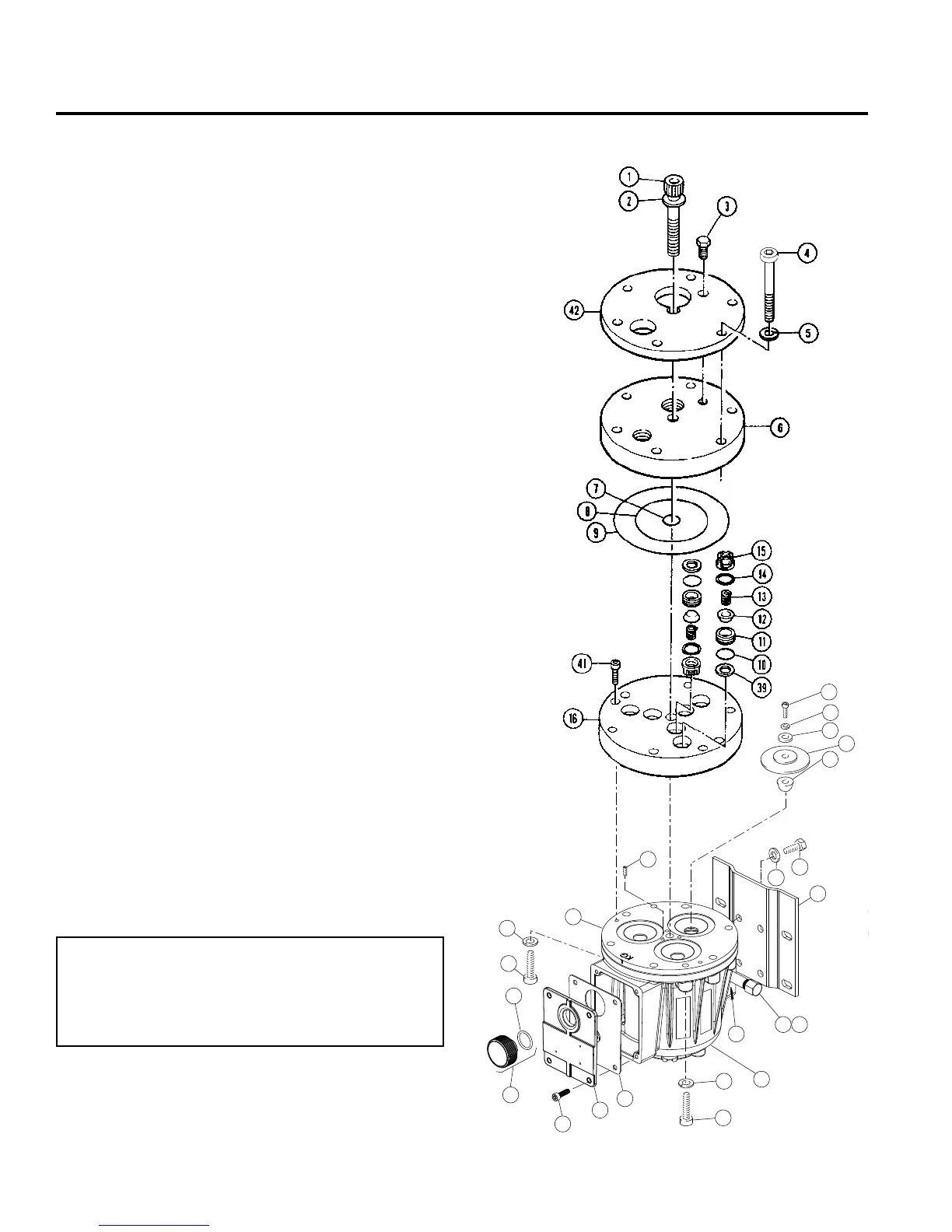
D/G-10 Service (Fluid End)
Model D-10/G-10
With Non-Metallic Pump Head*
NOTE: The numbers in parentheses are the Reference
Numbers on the exploded view illustrations found in this
manual and also in the Parts Manual.
This section explains how to disassemble and inspect all
easily-serviceable parts of the pump. Repair procedures for
the hydraulic end (oil reservoir) of the pump are included in a
later section of the manual.
CAUTION: Do not disassemble the hydraulic end unless
you are a skilled mechanic. For assistance, contact Wanner
Engineering (TEL 612-332-5681 or FAX 612-332-6937) or
the distributor in your area.
CAUTION: The two bolts (29; 25 or 44) that screw through
the back of the housing into the cylinder casting hold the
casting over the hydraulic end of the pump. Do not remove
them except when repairing the hydraulic end.
1. Remove Manifold (6), Valve
Plate (16)
a. Remove all nuts (31) and bolts (4) around the manifold. Do
not remove two bolts (29; 25 or 44) that are installed through
back of pump housing.
b. Use 3/8-in. (10-mm) hex Allen wrench to remove center
bolt (1) and its washer (2).
CAUTION: Do not turn the pump drive shaft while the
manifold and valve plate are off the pump, except
when removing diaphragms or repriming the hydraulic
cells.
c. Remove manifold (6), and support plate (42) [non-metallic
pump head only]. Valve plate (16) will remain on cylinder
casting (24).
d. Inspect manifold for warping or wear around inlet and outlet
ports. If wear is excessive, replace manifold.
To check if manifold is warped, remove O-rings and
place straightedge across it. Warped manifold should be
replaced.
*NOTE: For non-metallic slurry duty pumps, see the
insert to this manual for fluid valve service (Step 2),
then proceed to Step 3 in this manual for remaining
service steps.