5
4. Alarm Explanation: Rising and Falling Alarms
a. Rising: If the Danger (Low Level Alarm) is set to a lower value than the Alarm (High Level
Alarm), then the GA-170 will automatically configure the channel as a Rising Alarm (i.e., if
the sensor reading is higher than the Danger or Alarm settings, then the GA-170 will activate
alarm conditions).
b. Falling: If the Danger (Low Level Alarm) is set to a higher value than the Alarm (High
Level Alarm), then the GA-170 will automatically configure the channel as a Falling Alarm
(i.e., if the sensor reading is lower than the Danger or Alarm settings, then the GA-170 will
activate alarm conditions).
c. Failsafe Alarms: If a sensor channel is set to Failsafe, then the corresponding High Level
alarm relay will normally be energized. This will cause to reverse the NC/NO connections.
Therefore, the NC connections will be OPEN unless an alarm condition is present or power is
lost.
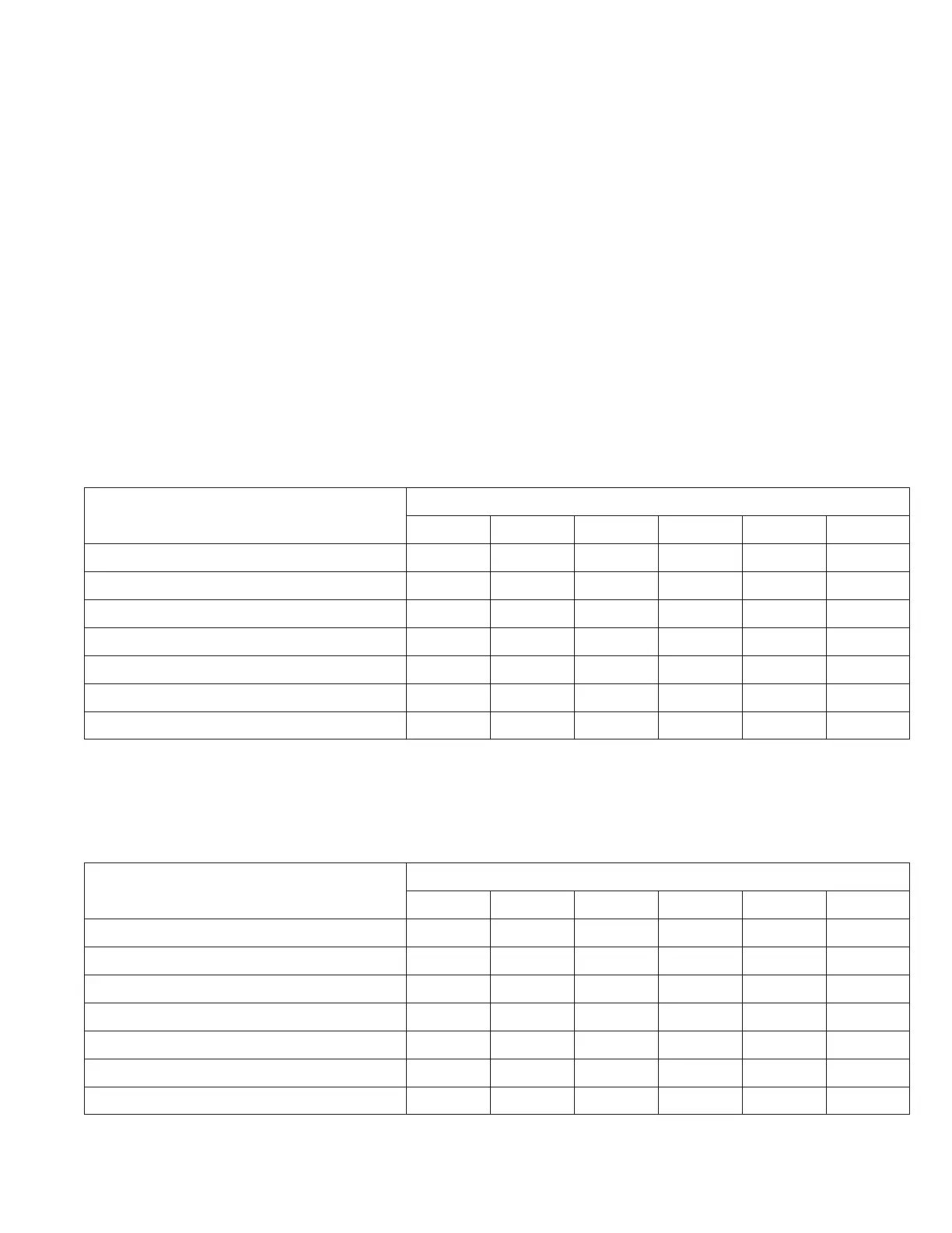
5. ALARM REFERENCE CHART (For one or two sensor units)
O – Inactive
X – Active
Alarm Relay
Condition 1 2 3 4 5 6
Lost A/C Power O O O O X O
Lost Battery Power O O O O X O
Lost Sensor 4-20mA O O O O O X
Low Level Alarm Sensor #1 X O O O O O
High Level Alarm Sensor #1 O X O O O O
Low Level Alarm Sensor #2 O O X O O O
High Level Alarm Sensor #2 O O O X O O
6. ALARM REFERENCE CHART: (For three or four sensor units)
O – Inactive
X – Active
Alarm Relay
Condition 1 2 3 4 5 6
Lost A/C Power O O O O X O
Lost Battery Power O O O O X O
Lost Sensor 4-20mA O O O O O X
High Level Alarm Sensor #1 X O O O O O
High Level Alarm Sensor #2 O X O O O O
High Level Alarm Sensor #3 O O X O O O
High Level Alarm Sensor #4 O O O X O O