4
7. Calibration: The Model GA-170 Gas Detectors are factory calibrated and do not require any
calibration at startup. With the use of the calibration cap, the span calibration can be carried out
if required. Be sure to retain the sensor calibration cap for such calibrations.
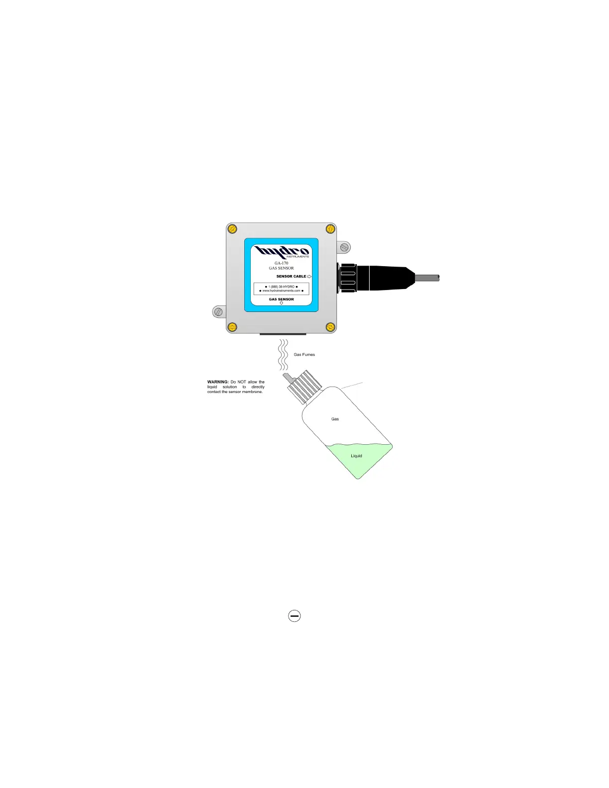
8. Response Checks (Bump Testing): To verify responsiveness, the gas sensors can be bump
tested (exposed to a small amount of the target gas) in order to test the reaction of the sensor.
A plastic squeeze bottle is provided with each gas detector for this purpose. See Figure 3. It is
suggested that bump testing can be done at quarterly intervals, however required frequency is
determined by environment, conditions, number of and severity of leaks. Proper bump testing
(exposing the sensor to a modest amount of the fumes) will not substantially degrade the sensor
or shorten sensor life. Depending on the environment, sensors can reliably last more than 5 years.
WARNING: Do NOT allow the liquid solution to directly contact the sensor membrane.
9. LED Indicators: If the sensor reading remains below the low alarm set point, then neither LED
will illuminate. If the reading rises above the low alarm set point, then the “DANGER” LED
will illuminate. If the reading rises above the high alarm set point, then the “ALARM” LED will
illuminate.
B. Alarms and Output Signals
1. Acknowledgement of Alarms: If an alarm condition occurs, the alarm (red) LED will
illuminate and the relay will be activated. To acknowledge an alarm (and thereby de-activate
[open] the relay contact output) press the
key.
NOTE: Even after acknowledging the alarm, both LEDs will remain illuminated until the alarm
condition has been removed.
2. 4-20 mA output channels: A 4-20 mA output signal can be obtained from each sensor
according to the wiring diagram (Figure 12). See Figures 9 through 13.
3. Alarm Relay: The GA-170 has six alarm relay outputs. The non-powered relays offer both
normally open and normally closed connections. See Figures 9 and 10. See suggested relay
wiring diagram (Figure 11).
FIGURE 3: Bump Testing (Chlorine Gas Example)
Bump Test Bottle
For Chlorine sensors
bottle contains 2 parts
NaClO solution (bleach)
and 1 part vinegar