6
FIGURE 4
7. RS-232 Output: Digital data output.
a. Use a standard “COM” cable with a DB9 connector and make the following connections:
DB9 Connector GA-170 Connections
2 TX
3 RX
5 GND
b. Run the Windows program “Hyperterminal” or any other terminal program. Set the COM
communications as follows:
Flow Control: none
Baud: 19,200
Format: 8 data bits, 1 start bit, 1 stop bit, no parity
C. Operation Screens
This section explains the features of the standard operating screens of the GA-170.
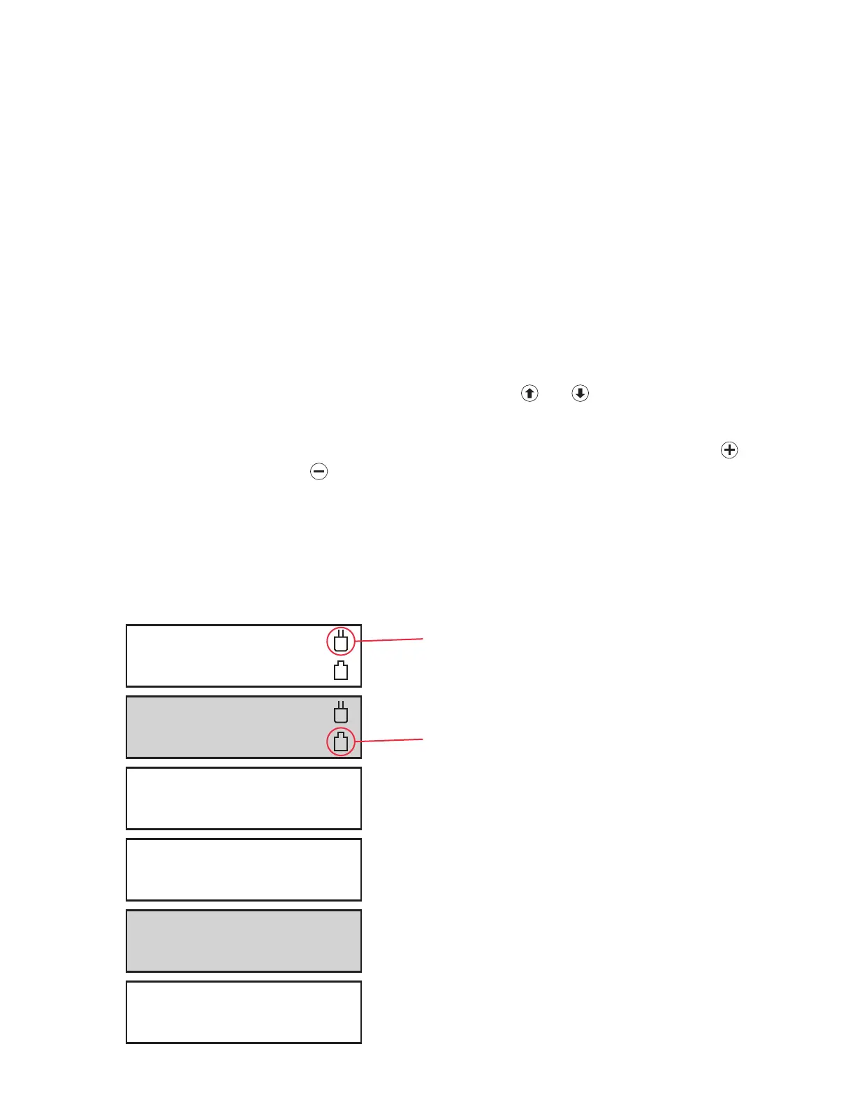
NOTE: Navigate between the display screens below using the
and keys. See Figure 4.
1. Home Screens (1 & 2): These screens display the gas type and reading of the sensor(s).
2. Test Operation (3): This screen allows manual testing of the horn and relays. Pressing
will
activate the horn. Pressing
will activate all relays.
3. Status Screens (4 & 5): These screens display all present alarm conditions.
4. Password Screen (6): See Section II.A for instructions on this screen and the configuration
section.
1 Cl2 0.0 PPM
2 CO 0.0 PPM
Test Operation
+ Horn – Relays
Enter Password
0 OK
GA-170 Operation Mode Screens
3 NH3 0.0 PPM
4 SO2 0.0 PPM
1 Status: Normal
2 Status: Normal
3 Status: Normal
4 Status: Normal
This icon indicates that A/C Power
is connected to the instrument.
This icon indicates that Battery Power
is connected to the instrument.
1
2
3
4
5
6
NOTE: The shaded screens
in Figure 4 are not shown
unless sensor 3 or sensor 4
is activated.