16
FIGURE 12
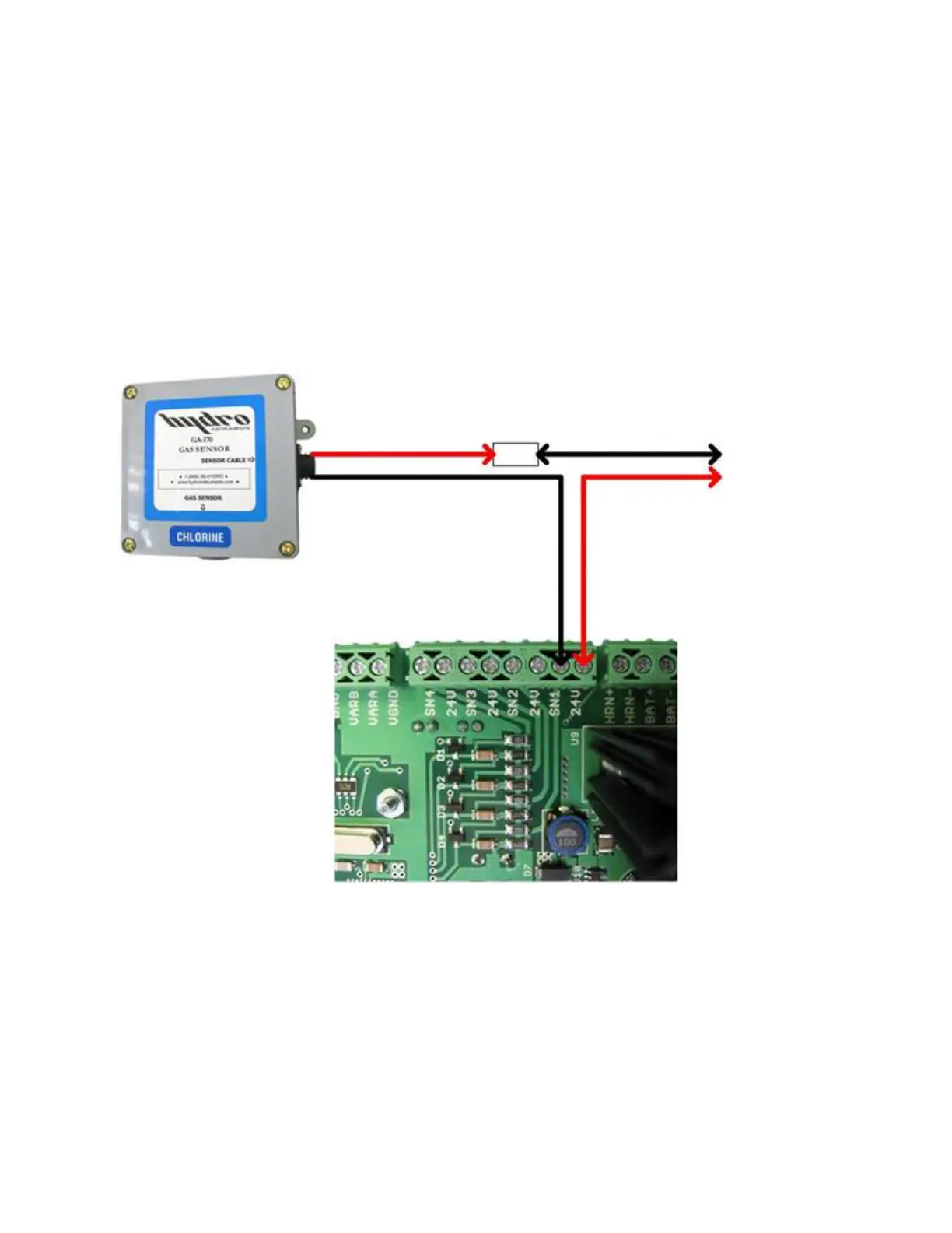
GA-170 Gas Alarm 4-20 mA Output:
1. Remove the red sensor wire from the 24V circuit board terminal.
2. Splice the red sensor wire to the black wire in the signal cable.
3. Connect the red wire in the signal cable to the same 24V circuit board terminal that was being
used.
NOTE: If the 4-20 mA output is not connected to a device the circuit will not be complete and the
sensor will not function. You may short the wires together to complete the circuit if not utilizing the
4-20 mA output.
Red Sensor Wire
Splice
4-20 mA
Output
Black Sensor Wire
To SN1 on
Circuit Board
To 24V on
Circuit Board
To p
Bottom
Black Signal Wire
Red Signal Wire