24
4.OPERATION AND USE
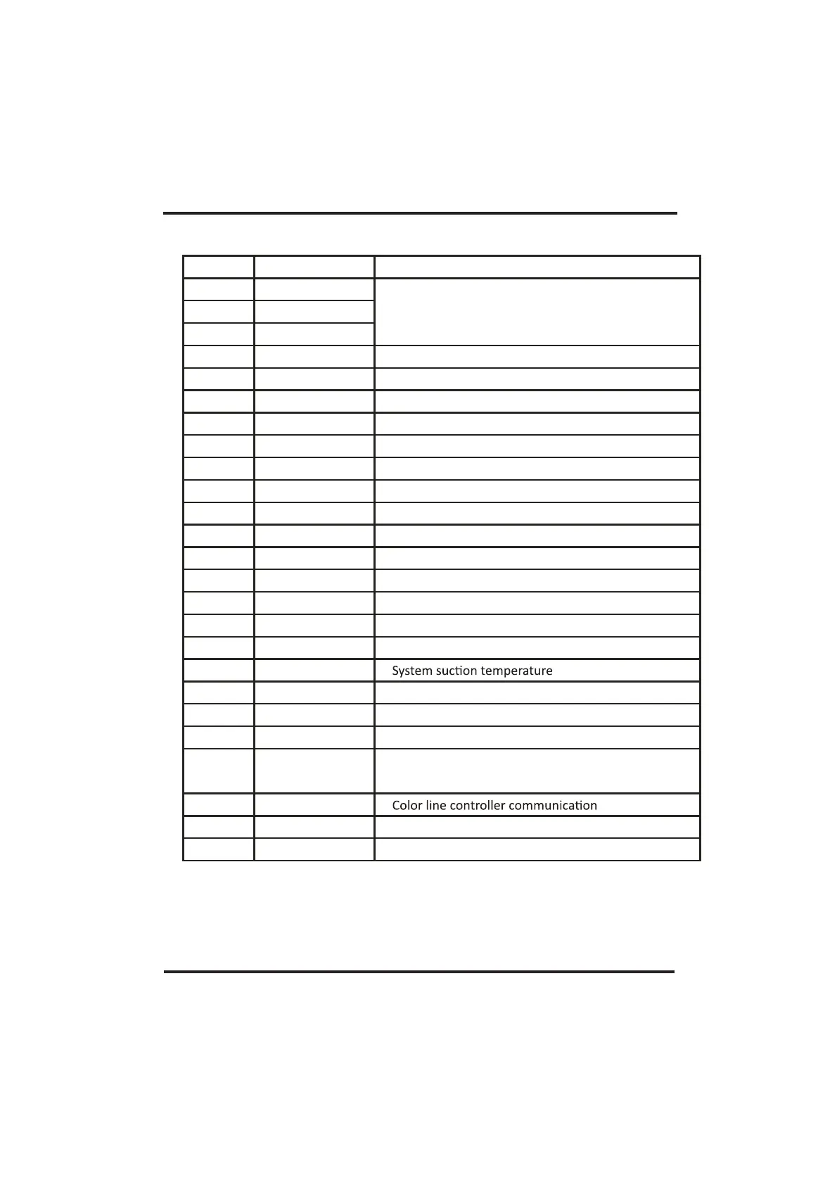
Main board of the input and output interface instructions below
Number Sign Meaning
01
02
03
04
05
06
07
08
09
10
11
12
13
14
15
16
17
18
19
20
21
22 Electric reactor
23
24
25
Centralized Control
Electronic expansion valve
P10-(U)
P10-(V)
P10-(W)
CN18(PUMP)
CN11(FOUR)
CN97
P1(AC-L)
P2(AC-N)
CN99(PL)
CN42(HP)
CN42(LP)
CN42(FS)
CN42(REMOTE)
CN42(MODE)
CN30(IT)
CN30(OT)
CN30(CT)
CN30(SUT)
CN30(AT)
CN30(ET)
P00(GND)
P13(L)
P14(L)
R485
RS485-2(CC)
CN15
Compressor ( output 220-230VAC)
Water pump ( output 220-230VAC)
4-way valve ( output 220-230VAC)
DC Fan
Live wire ( input 220-230VAC)
Neutral wire ( input 220-230VAC)
Pressure sensor
High pressure switch(input)
Low pressure switch(input)
Watow switch(input)
Remote switch(input)
Rerserve
Water input temperature(input)
Water output temperature ( input )
System fan coil temperature( input)
(input)
Ambient temperature( input)
System Exhaust temperature (input)
Earth wire