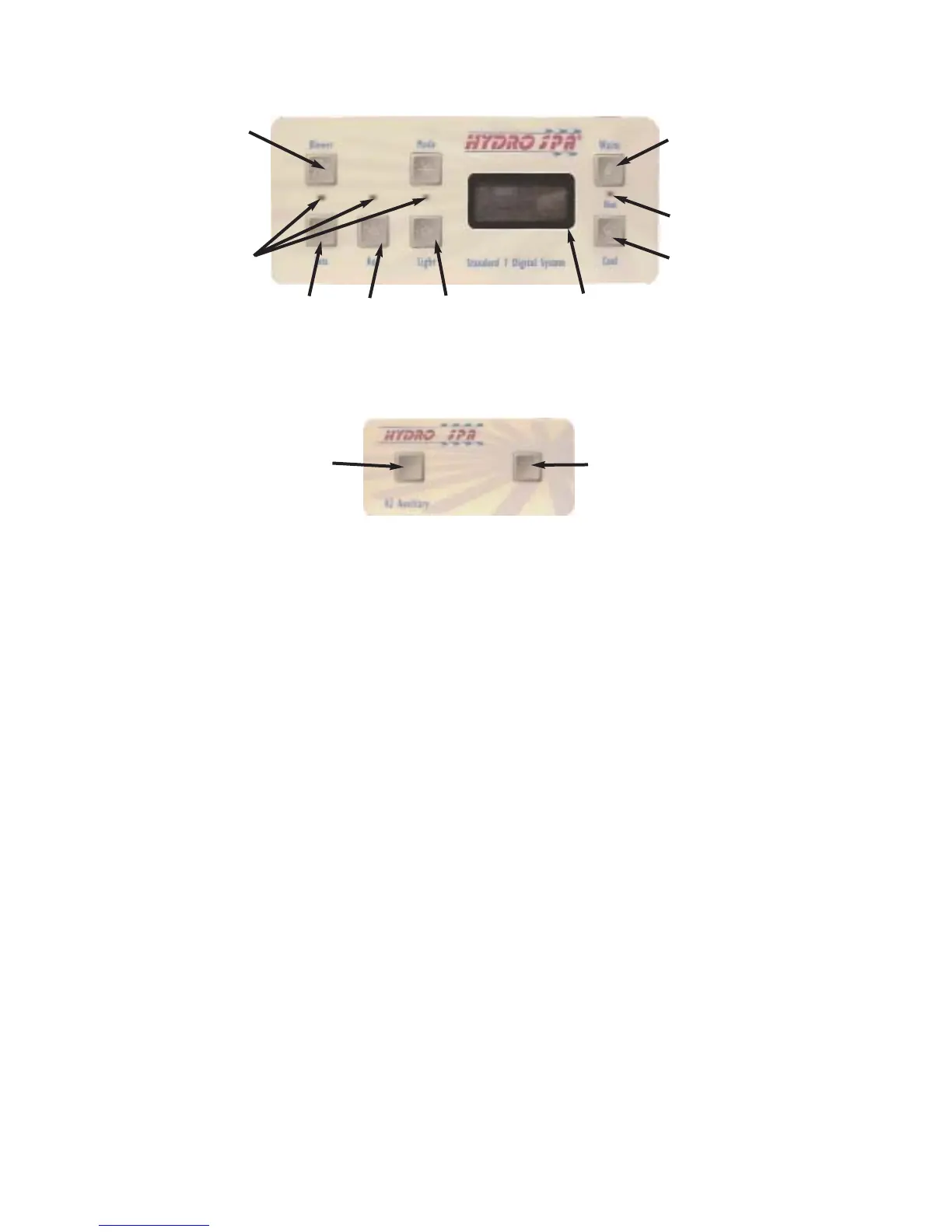
Blower
LED
Indicators
Jets 1
Aux
(Jets 2)
Light
Warm
Heat
Indicator
LED
Cool
Main Control Panel
Control Panel Display
Jets 1
Jets 2
Auxiliary Control Panel
Figure 8
OPERATING INSTRUCTIONS - HS200 M7
Your spa is equipped with a Topside control panel, air control knobs, on-off waterfall valve and an
aroma -therapy canister. Some models equipped with an auxiliary control panel. All controls located
on the top rail of the spa. These controls let you operate many of the special functions on your spa.
The main control panel controls all of the spa functions and uses indicator LED lights, LCD display to
aid the user to determining the status of the spa. Auxiliary control panel (if equipped) is conveniently
located on top rail so that a user inside of spa can operate the both pumps. By familiarizing yourself
with following information, you will be able to gain the full benefit afforded by the various functions of
your spa.
1. Main Control Panel
The main control panel provides quick visual check on the spa's status, and allows the user to adjust
the temperature set, activate the pumps, blower, light, control of the spa status.
The control panel activates functions at the touch of a button. The panel will also display diagnostic
messages which enable you to easily operate your spa and know about the spa's condition. See
"Display messages for details" Page 21.
Temperature Adjustment
To adjust your spa temperature by pressing the WARM or COOL button pad. When the
pad is pressed, the display will show the set temperature. Pressing the WARM button
will cause the set temperature to increase or pressing the COOL button pad to
decrease. The temperature adjustment range is 80°F-104°F.
Default setting is 100°F. Any interruption of power will cause the unit to reset and revert
to the default programming of 100°F set point.
Figure 9b
18