Installation Manual 5.1.2
14
6.0 The Ground Loop System
IMPORTANT! Do NOT use PVC or CPVC piping on any
connections to your Hydro-Temp unit. The only
exception where PVC or CPVC piping may be used is on
the condensate lines.
6.1 Closed Loop Systems Plumbing
Closed loop systems will require a minimum of 3 G.P.M.
per ton if the ground loop is designed to maintain a loop
temperature above 32ºF and below 90ºF. If design
temperatures are outside of these temperatures more
flow will be needed.
On residential systems typically a pump is required for
each unit. The loop pump requirement will depend
upon the loop design for a given application. The
ground loop piping system must provide suitable access
for purging the outside loop and require isolation valves
for purging the inside plumbing including the system.
To properly purge a closed loop system, a minimum
velocity of 2 feet per second in every branch of the
ground loop must be achieved. The purge ports will also
be used for anti-freeze charging.
IMPORTANT NOTICE: UNITS THAT UTILIZE GROUND
LOOPS MUST MAINTAIN A MINIMUM OF 20%
METHANOL OR 25% PROPYLENE GLYCOL AS
ANTIFREEZE SOLUTION IN THE UNIT AND GROUND
LOOP AT ALL TIMES. FAILURE TO DO SO WILL FREEZE
THE SYSTEM AND CAUSE SEVERE DAMAGE TO THE
UNIT.
DAMAGE TO THE UNIT CAUSED BY THE FAILURE TO
MAINTAIN PROPER ANTIFREEZE LEVELS IS NOT
COVERED UNDER THE WARRANTY.
It is recommended to always mount the ground loop
pump vertically so air will not be trapped in the pump if
not properly purged. A dry or air locked pump will
quickly burn out.
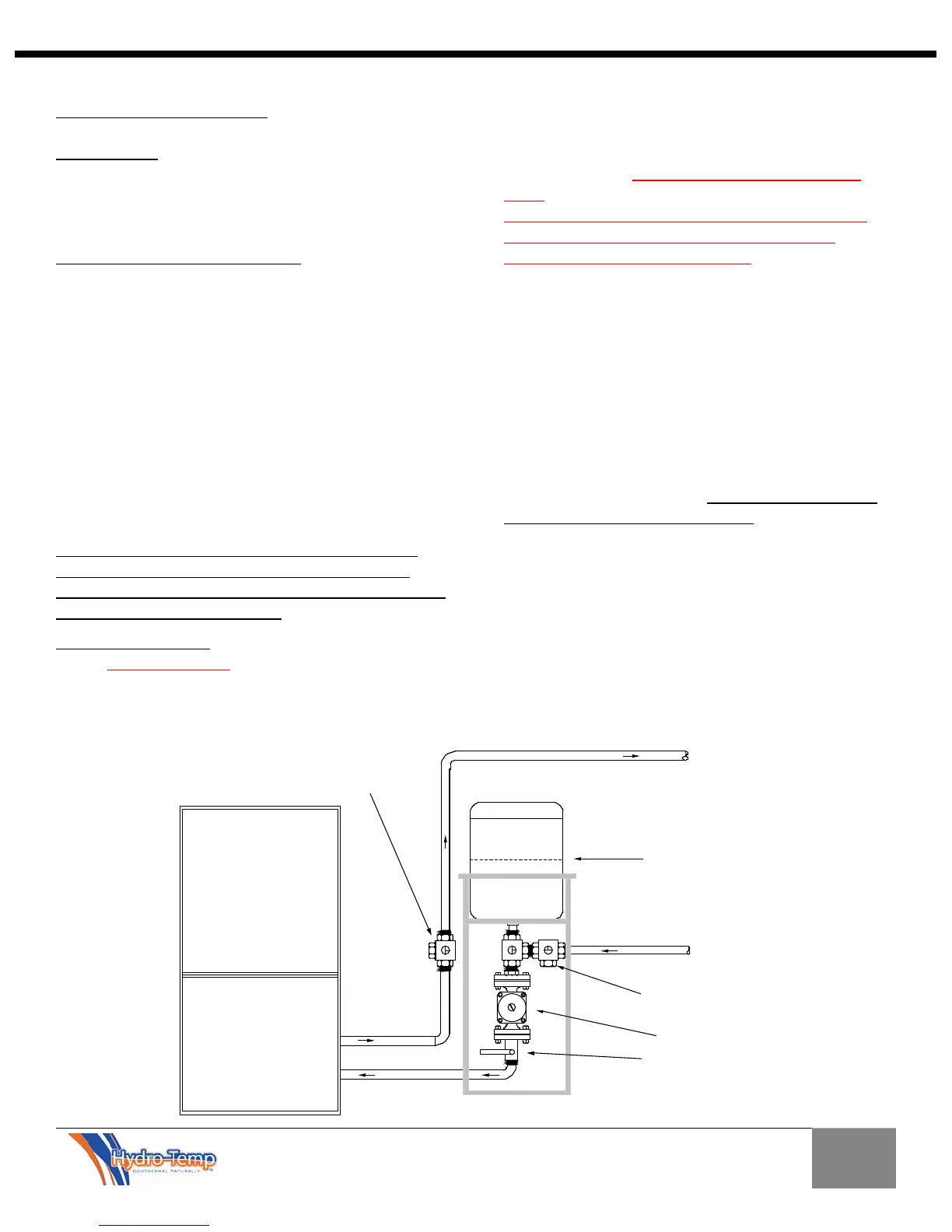
The recommended auto purge kit (shown below) is
designed with the pump mounted vertically and tees
strategically placed to purge air from the system and
into the auto purge tank automatically while running
(this should be used to remove small amounts of air left
after purging the system with the purge pump, or a
system pump replacement). The auto purge kit is not
used in place of purging the system but is left on the
system to purge the loop continuously. Systems with
the auto purge kit are not pressurized.
Pump
To Unit
From Unit
To Loop
From Loop
Auto-purge
Hydro-Temp
Flanged Shut off Valve
Kit
1" Purge Port on 3-Way
Valve. All 3 valves are the
same as discibed above.
This pipe is normally ran behind
Auto purge or through auto purge.
33" from here to base. Tank
can be cut here to fit in tight
spaces.
3 Way valve with purge port. Flow
direction can be determined by
indicator on valve stem. Flow can
be through any two directions or all
three directions.