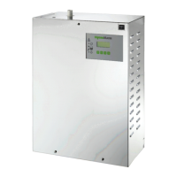
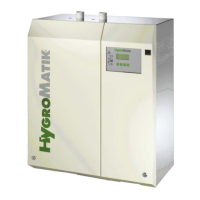
Page 18
5.7.3 Steam line and condensate
hose installation types
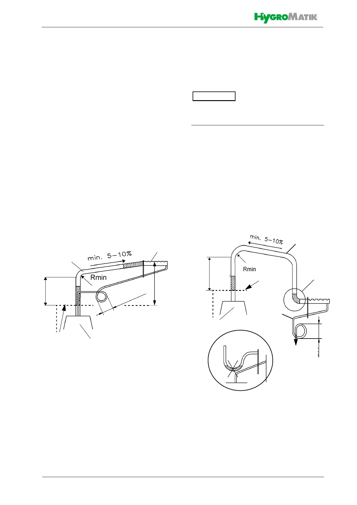
Installation type 1
Steam manifold is positioned more than
500 mm above device upper edge:
» Run steam hose to a height of 400
mm/16 inch minimum above the
steam humidifier and then to the
steam manifold with a continuos
incline of 5 to 10 %.
» Feed condensate hose from steam
manifold with a decline into waste-
water pipe or drain.
» As a steam barrier, lay out a 200
mm/8 inch min. loop (s. schematic
representation below). Minimum dis-
tance from steam manifold to loop
must be 500 mm/20 inch. Fill loop
with water prior to steam humidifier
commissioning.
Installation type 2
Steam manifold is positioned less than
500 mm above or below device upper
edge:
In this arrangement the condensate hose
cannot be fed back to the steam humidifier.
» Run steam hose to a height of 400
mm/16 mm minimum above the
steam humidifier and then to the
steam manifold with a continuos
decline of 5 to 10 %.
» Feed condensate hose to a waste-
water pipe/drain with a 200 mm/8
inch diameter loop as a steam bar-
rier. Minimum distance from steam
manifold to loop must be 500 mm/20
inch. Fill loop with water.
Steam cylinder
Steam manifold
Steam
hose
C
o
n
d
e
n
s
a
t
e
h
o
s
e
Installation type 1,
Device
upper edge
schematic representation
500 mm
20 inch
min.
400 mm
16 inch
2
0
0
m
m
/
8
‘
‘
m
i
n
Rmin
DN25: 200 mm/8 inch
DN40: 400 mm/16 inch
Steam cylinder
Steam
hose
Device
upper
Condensate
hose
Drain
Detail „x“
wrong!
Installation type 2,
schematic representation
edge
Detail „x“
Rmin
DN25: 200 mm/8 inch
DN40: 400 mm/16 inch
400 mm
16 inch
200 mm
8 inch