Page 19
5.8 Steam Manifold
5.8.1 General installation guidelines
When installing steam manifolds, pls. follow
these guidelines:
Positioning within duct
• Install the steam manifold as close as
possible to the steam humidifier in
order to minimize steam loss through
condensation
• Steam manifold placement on the sup-
ply side of the air duct is preferable
• Install steam manifold strictly horizontal
in order to ensure proper condensate
drain
• Shown installation and positioning
dimensions are based on empiric
values. Special environmental conditi-
ons may require adjustments. Pay
special attention to avoid condensate
generation in air duct
Allowable pressures
• Max. allowable pressure in air duct is
1500 Pa/.218 PSI (exemption: SLE02,
SLH02, KIT E02 and KIT H02 only
allow for 1200 Pa/.174 PSI)
• On suction side, max. -500 Pa (.07
PSI) is tolerable
• With high-pressure air conditioning
systems, modifications of the unit‘s
drain hose system may possibly be
required depending on the overall pres-
sure situation. These modifications
must be coordinated with your
expert dealer.
Water drain
• We point out that according to the Ger-
man Association of engineers (VDI)
guideline VDI 6022, a water drain must
be provided within the absorption
distance inside the air duct
When increased airflow speed is encoun-
tered
• Air flow rates beyond 3m/s (9.84 ft/s)
may lead to condensate drainage prob-
lems at the steam manifolds due to
vacuum built-up. A possible remedy is
twisting the steam manifold in its hori-
zontal axis by few angular degrees. In
case of problems, pls. consult your
expert dealer.
5.8.2 Recommendations for dimen-
sioning
The recommendations given below are
based on homogenous air flow in the duct.
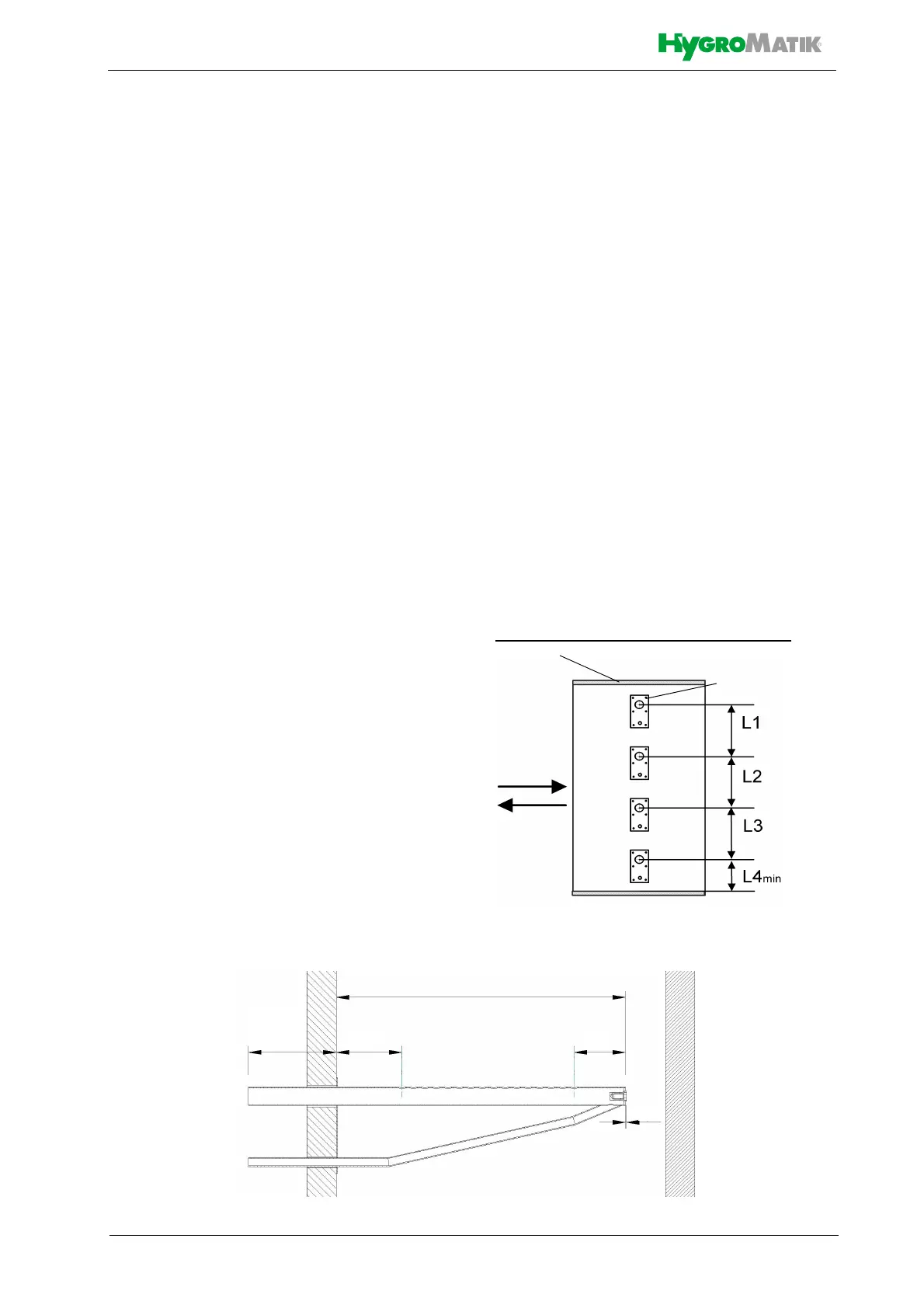
Horizontal installation of steam manifold
Standard steam manifold arrangement:
An even distribution of steam manifolds ensu-
res a uniform steam distribution.
Please use the
total hight of the
duct!
L1=L2=L3
Air flow
direction
Steam manifold
(Side view)
Air duct
*) s. table of manifold lengths Horizontal assembly position in duct
l*) (depends on duct dimension)
4.7 inch
3.5 inch
2.8 inch
120 mm 90 mm 70 mm
1.5 mm
.06 inch