Page 25
7.2 Safety interlock
The descriptions following hereafter relate to
the usage of a kit in combination with a
HygroMatik control.
Risk of electrical shock!
Hazardous electrical voltage!
When standard wiring was made, terminal 1
shows 208 - 240 VAC after commisioning.
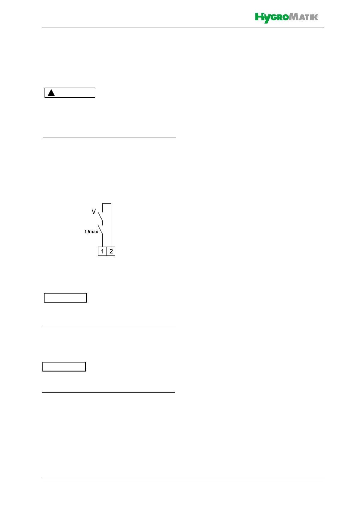
Across terminal 1 and 2 the so-called safety
interlock is wired. This wiring allows for inte-
gration of safety devices. In case of an open
safety interlock the steam humidifier does not
operate.
Factory setting leaves the safety interlock
open!
Install contact interlocks, e.g. a max. hygro-
stat in series across terminal 1 and 2.
Contacts across terminals 1 and 2 must be
potential free and rated for 240 VAC.
Best practice implies the integration of a max.
hygrostat in the safety interlock wiring to pro-
tect against over-humidification due to a r.h.
sensor malfunction.
7.3 Connection diagrams
In case of a HygroMatik control „Standard“ to
be used with the kit, The device-specific
wiring diagrams are included in the scope of
delivery. Please use them for the installation
and keep them in a safe place.
For all other types of use, the connection of
the electrical components is the responsibility
of the customer.
Safety interlock terminals 1/2