Page 33
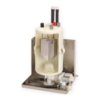
9.4 Removal and installation of
unit components
9.5 Blow-down pump (removal,
cleaning, reinstallation)
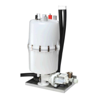
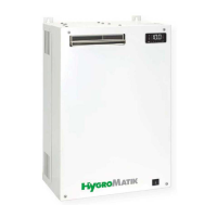
Removal and cleaning
» Remove steam cylinder as descri-
bed in „Removal of steam cylinder“
section.
» Detach adapter (30) from pump
(32).
» Detach electrical cable from pump.
» Remove nuts securing pump on
console bottom plate.
» Remove cap nuts securing cylinder
base ((37) in exploded view).
» Remove pump and cylinder base
from console and separate.
» Open pump bayonet lock.
» Remove residues from pump and
drain hoses (replace O-ring (34) if
required).
Reinstallation
» Moisten O-ring (33) and insert into
cylinder base (37) horizontal stub.
» Push pump back into cylinder base
and position the combination of
pump and base on the stud bolts of
the console.
» Reattach cap nuts (cylinder base)
and nuts (pump).
» Moisten O-ring (31) and insert into
adapter.
» Slide adapter (30) onto pump stub.
» Refit electrical cable to pump
connector (no polarisation).
» Follow the handling instructions in
the section Leakage test.
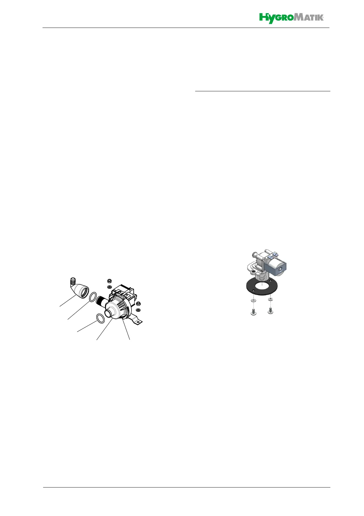
9.5.1 Solenoid valve (removal, rein-
stallation)
Removal
» Shut off water supply and disconnect
tap water hose cap screw connection.
» Remove connecting hose (20*) from
cylinder base.
» Detach electrical cable connector
from solenoid valve (25*).
» Unscrew solenoid valve mounting
screws.
» Remove solenoid valve from hous-
ing bore.
Reinstallation
» Reinsert fine filter into solenoid valve.
» Reinsert solenoid valve with seal in
unit housing bore.
» Bolt-down solenoid valve.
» Reestablish tap water connection.
» Reconnect electrical cable to sole-
noid valve.
» Reattach connecting hose (20) to
cylinder base using clamp.
» Follow the handling instructions in
the section Leakage test.
*) the numbers refer to the exploded view in the same
named chapter