WARNING
SHOCK HAZARD: Always turn off the power and
unplug the cord or set the line disconnect switch to
Off before servicing the unit or changing consumable
parts. In the U.S., use a “lock-out / tag-out” procedure
until the service or maintenance work is complete. In
other countries, follow appropriate national or local
safety procedures.
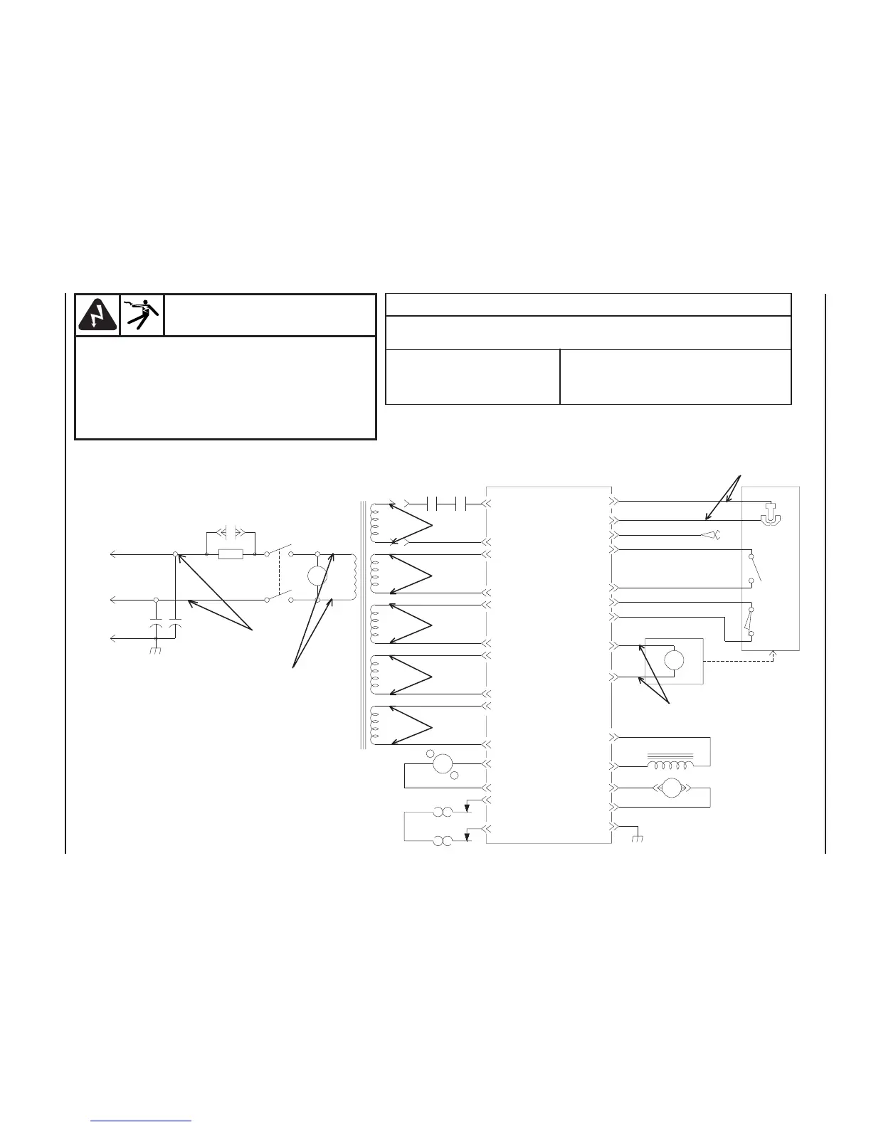
Voltage Readings
a) Tolerance ± 10 % unless specified
b) Reference - to circuit common, lead 43 unless noted
V1 230 VAC V7 24 VAC
V2 230 VAC V8 12 VDC
V3 227 VAC V9 320 VDC (open circuit voltage)
V4, V5, V6 20 VAC
Figure 5-2 Powermax190c 230 VAC Wiring Diagram
Power Supply 070069
Refer to Powermax190c Troubleshooting Guide in
Section 3.
V9
V8
V1
V2
V7
V6
V5
V3
V4