EasyManua.ls Logo

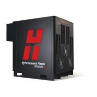
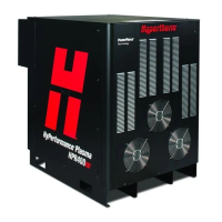
Hypertherm HyPerformance Plasma HPR400 User Manual

Hypertherm HyPerformance Plasma HPR400
355 pages
To Next Page IconTo Next Page
Page #1 background imageLoading...
Page #1 background image
HyPerformance
®
Plasma
HPR400XD
®
Auto gas
Instruction manual
806160 – Revision 4

Table of Contents

Questions and Answers:

Hypertherm HyPerformance Plasma HPR400 Specifications

General IconGeneral
Duty Cycle100% at 400 A
Cutting Capacityup to 50 mm (2 in)
Output Current30-400 A
Input Voltage200 – 480 V, 3-PH, 50/60 Hz
Gas SupplyOxygen, Air, Nitrogen

Summary

ELECTROMAGNETIC COMPATIBILITY (EMC)

Introduction

Overview of EMC compliance requirements for the plasma system.

Methods of Reducing Emissions

Techniques to minimize electromagnetic interference from the cutting equipment.

WARRANTY

General

Outlines Hypertherm's warranty coverage for defects in materials and workmanship.

Limitation of Liability

Specifies the limits of Hypertherm's liability regarding product use and damages.

Section 3 INSTALLATION

Installation Requirements

Guidelines for electrical and plumbing system installation conforming to codes.

Placement of System Components

Guidance on positioning system components before making connections.

Section 4 OPERATION

Daily Start-up

Procedures to follow before starting the plasma cutting system operation.

Consumable Selection

Guidance on choosing appropriate consumable parts for various cutting applications.

Section 5 MAINTENANCE

Routine Maintenance

Steps for regular maintenance tasks performed during consumable changes.

System Description

Explanation of the system components and their interconnections.

Section 6 PARTS LIST

Power Supply

List of part numbers and descriptions for the power supply unit.

Cooler

List of part numbers and descriptions for the system's cooling unit.

HyPerformance Torch

Components related to the HyPerformance torch assembly and its parts.

Section 7 WIRING DIAGRAMS

Introduction

Explains the format and organization of wiring diagrams in the manual.

Wiring Diagram Symbols

Identification and explanation of symbols used in wiring diagrams.

Appendix A HYPERTHERM TORCH COOLANT SAFETY DATA

2 – Hazards Identification

Information on potential hazards associated with the torch coolant.

Appendix B CNC INTERFACE PROTOCOL

Interface Hardware

Details on the physical requirements for the CNC interface connection.

Signal List

Lists and describes signals for the CNC interface. Includes Machine Motion and Plasma Start.

Serial Commands

Defines the format and commands for serial communication with the CNC.

Related product manuals