InstallatIon
HPR400XD Auto Gas – 806160 3-9
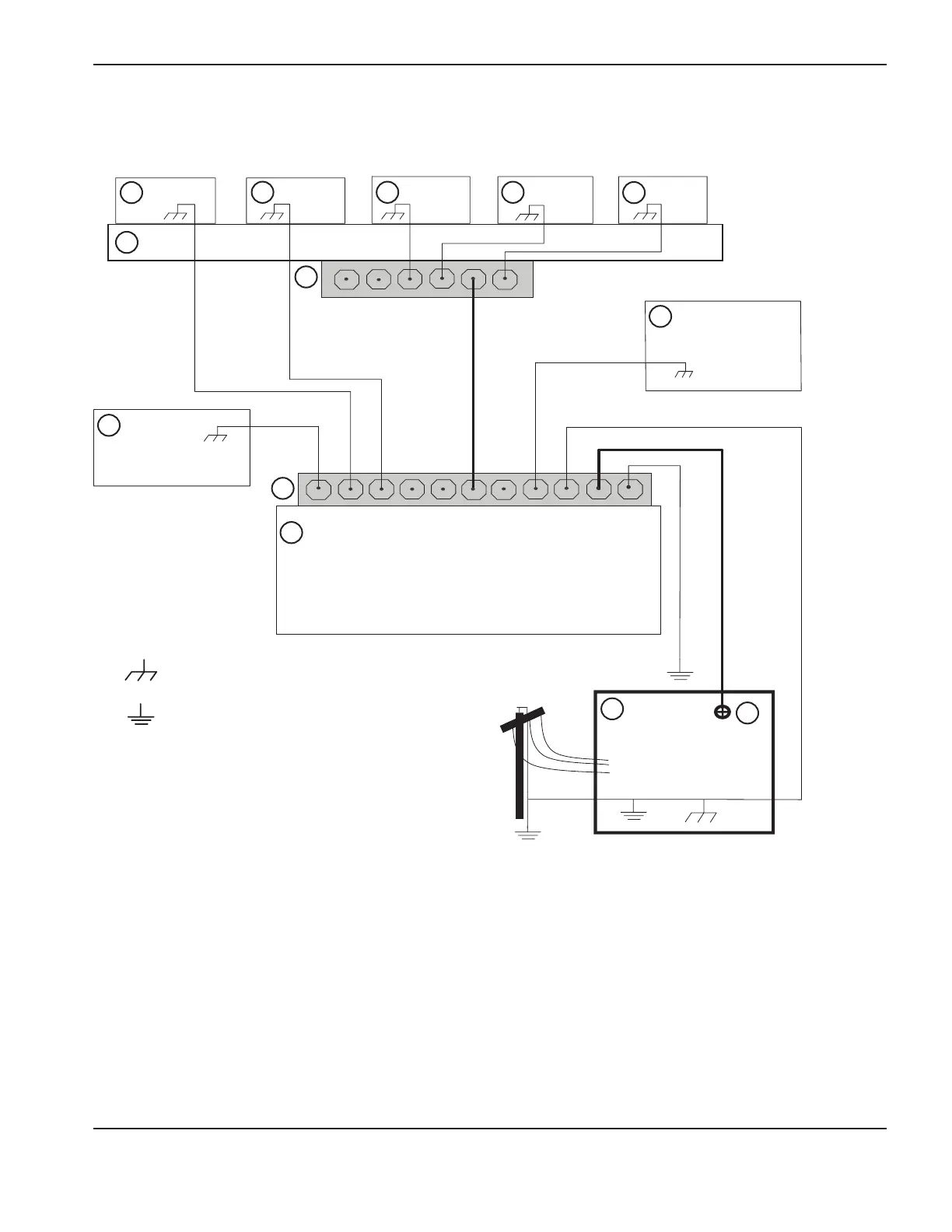
Grounding diagram
Grounding diagram
The following diagram shows an example of grounding the components in a plasma cutting system.
5
10
11
Chassis and RFI ground
AC earth ground
1 Cutting table
2 Gantry
3 Plasma system
4 Table ground bus bar
5 Gantry ground bus bar
6 Torch height control lifter (ArcGlide
®
,
Sensor™
THC, Sensor PHC, or other)
7 RHF console (not on all systems). Connect to
table ground bus bar.
8, 9 System-specific component such as metering
console, gas console, or selection console
10 CNC chassis
11 Torch height control module (ArcGlide,
Command
®
THC)
12 System-specific component such as a cooler or
chiller
13 DC power ground