EasyManuals Logo

Hypertherm HyPerformance Plasma HPR400 User Manual

Hypertherm HyPerformance Plasma HPR400
355 pages
To Next Page IconTo Next Page
To Previous Page IconTo Previous Page
Page #46 background imageLoading...
Page #46 background image
InstallatIon
3-8 HPR400XD Auto Gas 806160
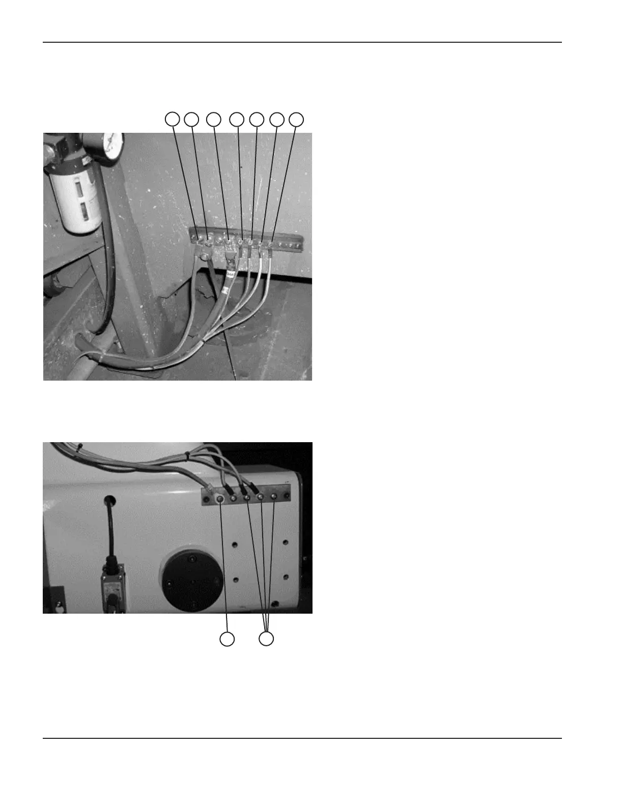
The following picture shows an example of a cutting table ground bus. The components shown here may differ from your
system.
1
2
3
4
5
6
7
1 Gantry ground bus
2 Ground rod
3 Plasma system lead (+)
4 Remote high frequency (RHF) console
5 CNC enclosure
6 Torch holder
7 Plasma system chassis
The following picture shows an example of a gantry ground bus. It is bolted to the gantry, close to the motor. All of the
individual ground cables from the components mounted on the gantry connect to the bus. A single heavy cable then
connects the gantry ground bus to the table ground bus.
1
2
1 Cable to the cutting table ground bus
2 Ground cables from components on the gantry

Table of Contents

Questions and Answers:

Question and Answer IconNeed help?

Do you have a question about the Hypertherm HyPerformance Plasma HPR400 and is the answer not in the manual?

Hypertherm HyPerformance Plasma HPR400 Specifications

General IconGeneral
Duty Cycle100% at 400 A
Cutting Capacityup to 50 mm (2 in)
Output Current30-400 A
Input Voltage200 – 480 V, 3-PH, 50/60 Hz
Gas SupplyOxygen, Air, Nitrogen

Related product manuals