5.
Reconnect 6way connector B, check pin 9 on connec-
tor A for +5V.
6.
If there is no voltage at A9 (+5V), then troubleshoot
the module. See the Troubleshooting Manual section.
7.
If the voltages are proper readings (in Step 4 and
Step 55), then check inputs at connector A while acti-
vating each function.
NOTE: Voltage should be present at A3, A4, A5, A6 and
ONLY while activating the corresponding function. See
Table 2.
8.
If the input values differ from those in the table, trou-
bleshoot the control handle components, controller,
and wiring. Make any necessary repairs, and recheck
the input values.
9.
If the input values are correct, replace the control mod-
ule. See Remove.
NOTE: ETACC may be used to check communication be-
tween control handle, control module, and traction control-
ler. See the Troubleshooting Manual section.
REMOVE
1.
Turn the key switch to the OFF position and discon-
nect the battery.
2.
Remove drive unit compartment covers for access to
the electrical components. See the section Periodic
Maintenance 8000SRM1644.
3.
Discharge the capacitors. See Discharging the Internal
Capacitors in this section.
4.
Disconnect all connectors from the control module.
5.
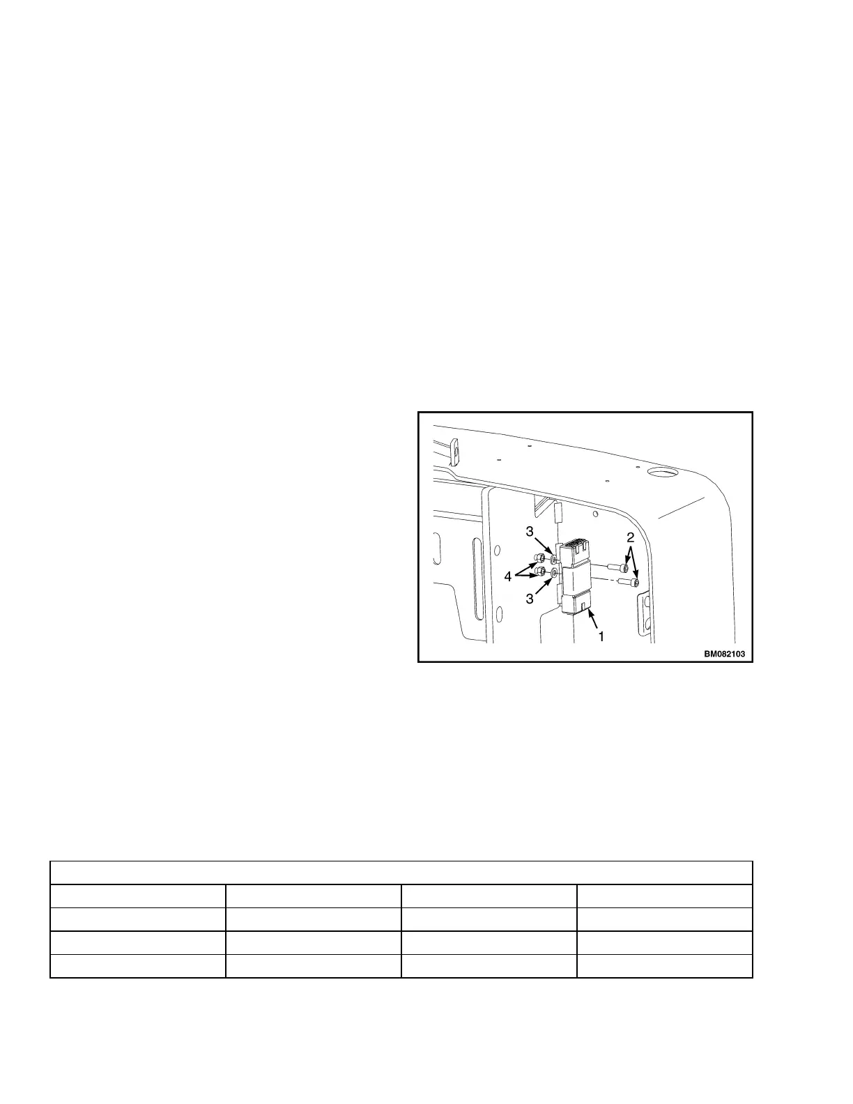
Remove capscrews, lock nuts, and washers securing
control module to the frame.
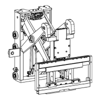
6.
Inspect the inserts. Replace as necessary. See Fig-
ure 20.
INSTALL
NOTE: Install new control module with the 16way con-
nector (A) orientation toward the floor mat.
1.
Position new control module frame.
2.
Install capscrews, washers, and lock nuts to secure
module to frame. Tighten to 3.5 N•m (31.0 lbf in).
3.
Install connectors to control module.
4.
Connect the battery and turn the key switch to the ON
position. Test truck for proper operation.
5.
Install the drive unit compartment covers. See the sec-
tion Periodic Maintenance 8000SRM1644. Test the
lift truck for proper operation, and return the truck to
service.
1. CONTROL MODULE
2. CAPSCREWS
3. WASHERS
4. LOCK NUTS
Figure 20. Control Module Mounting
Table 2. Input Connector A
16 Pin Connector A
A1 DI1 First Digital Input BS
A2 DI2 Second Digital Input SR
A3 DI3 Third Digital Input Horn
A4 DI4 Fourth Digital Input FWD
Control Module 2200 SRM 1640
20