Cylinder Head, Camshaft, and Valve Mechanism Repair 600 SRM 496
INSPECT AND REPAIR
Cylinder Head
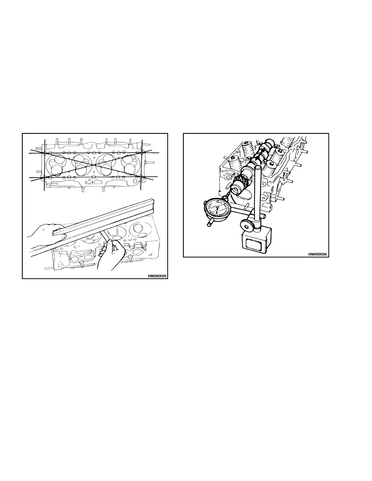
Use straight edge and thickness gauge to check bot-
tom surface of cylinder head for distortion. Do the
measurements at the positions shown in Figure 8.
Maximum amount of distortion is 0.15 mm
(0.0059 in.). If grinding of cylinder head is nec-
essary, maximum amount of correction is 0.2 mm
(0.008 in.).
Figure 8. Cylinder Head Inspection
Rocker Shaft Assembly
1. Disassemble rocker shaft assembly. Put marks
onrocker arms sothey can be installed on correct
shafts.
2. Clean oil passages in rocker shafts and rocker
arms.
3. Check clearance between rocker arms and
rocker shafts. Maximum clearance is 0.10 mm
(0.004 in.).
Correct dimension for inside diameter of rocker
armis16.000to16.027mm(0.6299to0.6311in.).
Correct dimension for outside diameter of
rocker shaft is 15.966 to 15.984 mm (0.6286 to
0.6293 in.). If components do not meet specifica-
tions, replace rocker arm(s) or rocker shaft(s) as
necessary.
Camshaft
1. Check camshaft for cracks or damage.
2. Use dial indicator on end of camshaft to check
movement of camshaft in cylinder head. See
Figure 9. Maximum movement is 0.20 mm
(0.008 in.).
Figure 9. Camshaft Check
3. Measureheightofcamshaftlobes. SeeFigure10.
Minimum height of intake and exhaust lobes is
36.902 mm (1.4528 in.).
4. Measure camshaft journals at four points (A-D)
asshowninFigure10.Minimumdimensionsfor
the journals are as follows:
Front and Rear Journals (Nos. 1 and 5) -
31.940 to 31.965 mm (1.2575 to 1.2585 in.)
Center Journals (Nos. 2, 3 and 4) - 31.910 to
31.935 mm (1.2563 to 1.2573 in.)
Front Oil Seal Surface - 33.961 to 34.000 mm
(1.3371 to 1.3386 in.)
Fuel Pump Lobe - 37.1 mm (1.46 in.)
5. Check camshaft for straightness. Put front and
rear journals in Vblocks and rotatecamshaft one
completeturn. SeeFigure11. Maximum amount
that the dial indicator should indicate is 0.03 mm
(0.0012 in.).
4
 Loading...