16
H70–110XL
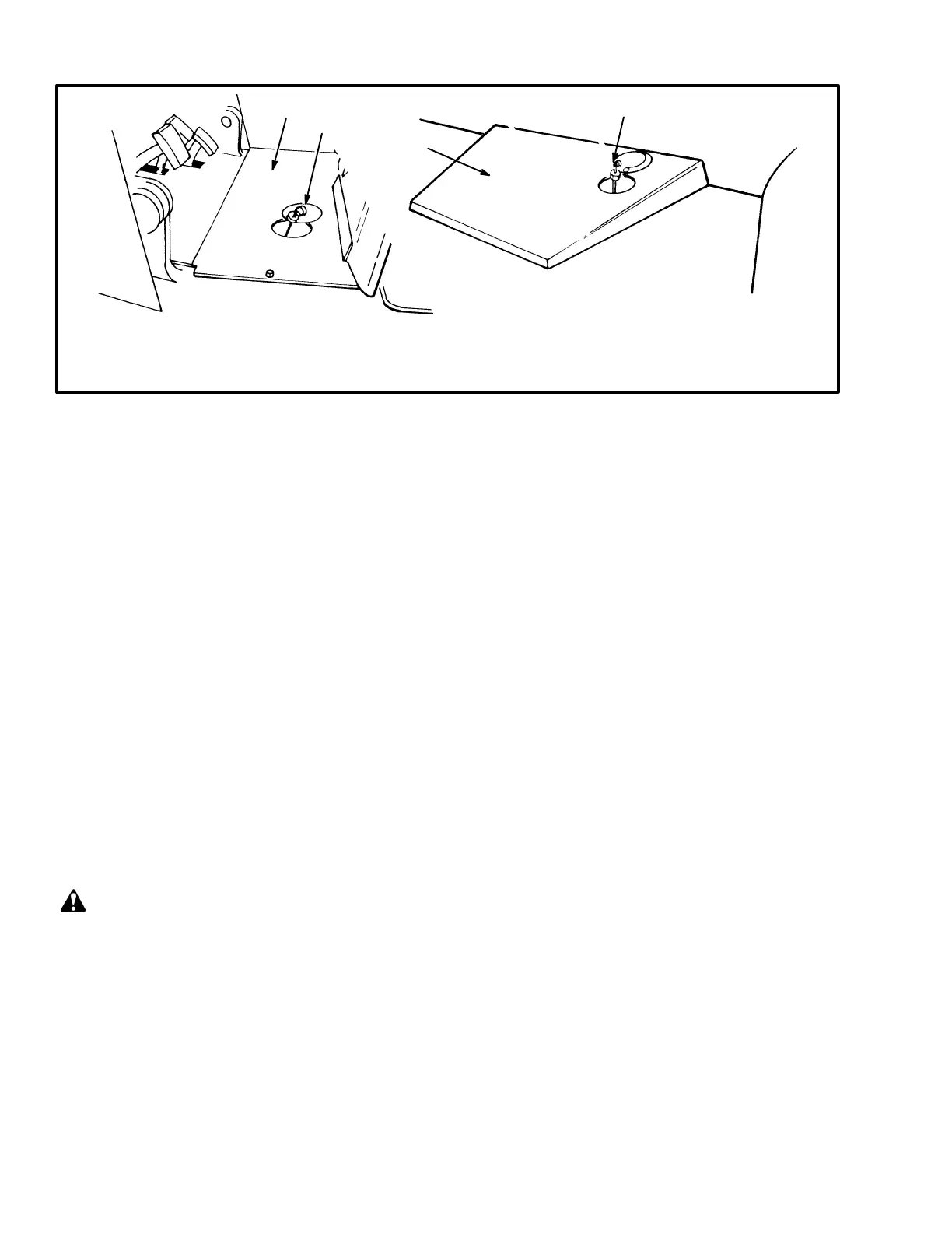
1. DIPSTICK FOR POWERSHIFT TRANSMISSION OIL OR OIL CLUTCH SYSTEM OIL
2. DIPSTICK FOR POWERSHIFT TRANSMISSION
3. FLOOR PLATE
H135–155XL
11703
11638
1
2
3
3
FIGURE 18. CHECK THE OIL FOR THE POWERSHIFT TRANSMISSION OR OIL CLUTCH SYSTEM
Oil Level, Oil Clutch System, H3.50–5.00XL
(H70–110XL) (See FIGURE 18.)
NOTE: The oil clutch system for the H6.00–7.00XL
(H135–155XL) lift trucks does not have a dipstick be-
cause the oil clutch uses oil from the hydraulic system.
Put the direction control lever in the NEUTRAL (N)
position. Apply the parking brake. Check the oil level in
the clutch housing when the engine is running at idle
speed. The most accurate check of the oil level is when
the oil is at operating temperature. Use the correct oil as
shown in the MAINTENANCE SCHEDULE. Keep the
oil at the “FULL” mark on the dipstick.
Control Levers and Pedals
Check that the control levers for the transmission, mast
and attachment operate as described in the OPERAT-
ING MANUAL. Check that the pedals operate cor-
rectly as described in the OPERATING MANUAL.
Lift System Operation
WARNING
Lower the lift mechanism completely. Never allow
any person under a raised carriage. Do not put any
part of your body in or through the lift mechanism
unless all parts of the mast are completely lowered
and the engine is STOPPED.
Before making any repairs, use blocks and chains on
the mast weldments and carriage so that they can not
move. Make sure the moving parts are attached to a
part that does not move.
Do not try to find hydraulic leaks by putting hands
on pressurized hydraulic components. Hydraulic oil
can be injected into the body by the pressure.
Do the following checks and inspections:
a. Check for leaks in the hydraulic system. Check
the condition of the hydraulic hoses and tubes.
b. Slowly raise and lower the mast several times
without a load. Raise the mast to its full extension
height at least once. The mast components must
raise and lower smoothly in the correct sequence.
NOTE: Some parts of the mast move at different speeds
during raising and lowering.
c. The inner weldments and the carriage must lower
completely.
d. Raise the mast one metre (three feet) with a ca-
pacity load. The inner weldments and the car-
riage must raise smoothly. Lower the mast. All
moving components must lower smoothly.
e. Lower the load to approximately 0.3 metre (one
foot). Tilt the mast forward and backward. The
mast must tilt smoothly and both tilt cylinders
must stop evenly.
f. Check that the controls for the attachment oper-
ate the functions of the attachment. (See the sym-
bols by each of the controls.) Make sure all of the
hydraulic lines are connected correctly and do
not leak.