Do you have a question about the Hyster J2.00-3.20XM and is the answer not in the manual?
Overview of the drive axle, speed reducer, and differential assembly.
Detailed description of the drive unit assembly components and function.
Procedures for removing the drive unit assembly from the lift truck.
Steps to take apart the drive axle, speed reducer, and differential.
Instructions for cleaning drive axle components using solvents.
Guidelines for inspecting drive axle parts for wear or damage.
Procedures for reassembling the drive axle components.
Steps for installing the drive unit assembly onto the lift truck.
Required torque values for various fasteners in the drive axle assembly.
Common problems and their solutions for the drive axle system.
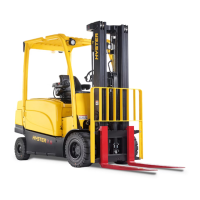
This document serves as a comprehensive service and repair manual for the Hyster A216 (J2.00XM, J2.50XM, J3.00XM, J3.20XM Europe) series, specifically focusing on the drive axle, speed reducer, and differential components. It also covers the J2.00-3.20XM (J40-60XM, J40-60XM2) [A216] and J2.00-3.20XM (J40-60Z) [A416] models. The manual is designed to guide technicians through the necessary procedures for maintaining and repairing these critical powertrain elements, ensuring the safe and efficient operation of the lift truck.
The drive unit assembly is a fundamental component of the lift truck's powertrain, responsible for transmitting power from the traction motor to the drive wheels. It comprises several interconnected systems: the drive axle, speed reducer, and differential.
The drive axle forms the structural backbone of the drive unit, providing the spindles for the wheel bearings at its outer ends. The wheel hubs, which house the wheel bearing cups, are secured to these spindles. Axle shafts, fastened by capscrews, connect the hubs to the internal drive mechanism. The back plate and brake assemblies are also integral to the axle mounts, facilitating the braking function.
The speed reducer and differential are integrated into a single unit. The speed reducer's primary function is to reduce the rotational speed from the traction motor and increase torque, preparing it for the differential. This is achieved through a series of gears: a pinion, which engages with the splines on the traction motor shaft, and a cluster gear that transfers power to the reduction gear.
The differential then takes the power from the reduction gear and distributes it to the drive wheels, allowing them to rotate at different speeds. This is crucial for turning, as the outer wheel needs to travel a greater distance than the inner wheel. The differential ensures smooth cornering by compensating for these speed differences. The drive gear on the differential is engaged with the reduction gear, completing the power transfer chain.
The drive unit assembly is designed for robust performance in industrial environments, enabling the lift truck to move and maneuver effectively. Its modular design, where the speed reducer and differential are combined, simplifies assembly and maintenance processes. The use of specific alignment pins and mounting arrangements facilitates precise installation and removal from the lift truck frame.
The system incorporates various fastening mechanisms, including capscrews, nuts, bolts, and lock plates, to ensure secure assembly and prevent loosening during operation. The wheel bearings are designed to handle significant loads, with preload adjustments made via a nut on the spindle. Lubrication is critical for the longevity of these components, with the outer wheel bearing lubricated by gear oil from the differential housing and the inner wheel bearing by wheel bearing grease.
The manual emphasizes a structured approach to maintenance and repair, prioritizing safety and precision.
Safety Precautions: Before any work begins, strict safety protocols must be followed. This includes disconnecting the battery connector (for electric trucks) or the battery ground cable (for internal combustion trucks), wearing safety glasses, and using appropriate lifting mechanisms for heavy parts. The lift truck must be securely placed on blocks to prevent rolling or falling, with additional blocks strategically placed to maintain stability, especially when removing heavy components like the drive axle, battery, or counterweight. A "DO NOT OPERATE" tag must be affixed to the controls.
Removal Procedures: Detailed steps are provided for removing the drive unit assembly. This involves disconnecting the battery, removing the mast assembly, and then using a crane and chains to lift the truck onto blocks. Subsequent steps include removing floor plates, drive wheels, brake lines, and parking brake cables, and draining the differential oil. Special tools and methods are outlined for removing alignment pins, which can be a tight fit.
Disassembly Procedures: Once the drive unit is removed, the manual guides the technician through disassembling its components. This includes removing axle shafts, brake assemblies, axle mounts, expansion plugs, and separating the speed reducer housing from the differential housing. Further disassembly involves removing bearing caps, gears, bearings, shims, and the drive gear from the differential case. Instructions are also provided for disassembling the differential itself if necessary.
Cleaning and Inspection: Thorough cleaning of all drive axle parts with a cleaning solvent and compressed air is mandated, with a strong emphasis on safety precautions for handling flammable and toxic solvents and using compressed air. Inspection is a critical step, focusing on checking gears for wear or damage, particularly spider and axle gears, and the cross for wear where gears turn. Bearings and their surfaces must be inspected for damage, and axle mounts must turn freely on the axle housing. The splines for the axle shafts must also be checked for damage.
Assembly Procedures: The assembly process is meticulously detailed, often requiring specific temperatures for components like the drive gear to facilitate installation. Lubrication of bearing cups and cones with axle lubricant is crucial. The manual provides precise instructions for installing side gears, thrust washers, the spider (cross), differential pinions, and reassembling the differential case, ensuring alignment marks are matched.
Adjustments and Torque Specifications: Critical adjustments, such as setting the drive gear location and applying preload to the differential bearings, are explained with specific torque values and rotational checks. The installation of bearing cups, O-rings, and housings requires the application of sealant. Torque specifications are provided for various fasteners, including capscrews for bearing caps, lock nuts for reduction gears, and bolts for securing the speed reducer housing to the differential housing.
Installation Procedures: The drive unit assembly is reinstalled using a floor jack, aligning bolt holes and alignment pins. Brake assemblies are reconnected, and new oil seals are installed in the hubs. Wheel bearing lubrication and lock nut tightening procedures are outlined, including specific torque values and alignment steps. Axle shafts, brake lines, wheels, and tires are reinstalled and tightened to specified torques. The differential housing is refilled with SAE 90 EP gear oil. Finally, the mast and battery are reinstalled, and the lift truck is removed from blocks.
Troubleshooting: A dedicated troubleshooting section helps diagnose common issues. It lists problems such as the lift truck not moving, drive axle leaks, or drive axle noise, along with possible causes (e.g., broken axle shaft, damaged differential, worn gears, damaged seals, low oil level) and corresponding corrective actions (e.g., install new parts, repair, tighten, fill).
This comprehensive manual ensures that all maintenance and repair tasks for the Hyster A216 series drive axle, speed reducer, and differential are performed accurately, safely, and efficiently, contributing to the overall reliability and performance of the lift truck.
| Model | J2.00-3.20XM |
|---|---|
| Power Source | Electric |
| Category | Forklifts |
| Battery Voltage | 48 V |
| Tire Type | Pneumatic |
| Overall Width | 1150 mm |