Service Manual
6. Baseband Section
6.1 Front Panel
6.1.1 Overview
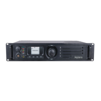
The front panel is the control panel, where you can see keys, Volume Control knob, Navigation knob,
LED indicator, LCD display and 10-Pin interface. The front panel is connected to the baseband board via
40-Pin FFC. See the following figure:
Figure 6-1 Front Panel Overview
6.1.2 Keys and Knobs
The keys on the front panel are controlled by key matrix of TX OMAP5912 (U102), and the Volume
Control knob and Navigation knob are controlled by GPIO of TX OMAP5912 (U102). See the following
figure:
KB_R0(G18)
KB_R1(F19)
KB_C0(F18)
KB_C1(D20)
KB_C2(D19)
TX OMAP5912
U102
GPIO4(P20)
GPIO6(P19)
GPIO46(W21)
GPIO49(L14)
GPIO26(AA9)
CH+/CH-
P1, P2, P3, P4
(2×3 Key matrix)
Volume control
knob
Menu navigation
knob
VOL_GPIO1
VOL_GPIO2
KNOB_A
KNOB_B
Baseband
Board
KNOB_C
Front
Panel
BOARD
Figure 6-2 Key and Knob Control Diagram for the Front Panel
6

 Loading...