EasyManua.ls Logo

Hyundai 35L-7A User Manual

Hyundai 35L-7A
210 pages
To Next Page IconTo Next Page
Page #1 background imageLoading...
Page #1 background image
0-1
FOREWORD
1. STRUCTURE
This service manual has been prepared as an aid to improve the quality of repairs by giving the
serviceman an accurate understanding of the product and by showing him the correct way to perform
repairs and make judgements. Make sure you understand the contents of this manual and use it to
full effect at every opportunity.
This service manual mainly contains the necessary technical information for operations performed in
a service workshop.
For ease of understanding, the manual is divided into the following sections.
SECTION 1 GENERAL
This section gives the general information of the machine and explains the safety hints for
maintenance.
SECTION 2 REMOVAL & INSTALLATION OF UNIT
This section explains the procedures and techniques of removal and installation of each component.
SECTION 3 POWER TRAIN SYSTEM
This section explains the structure of the transmission as well as control valve and drive axle.
SECTION
4 BRAKE SYSTEM
This section explains the brake piping, each component and operation.
SECTION 5 STEERING SYSTEM
This section explains the structure of the steering unit, priority valve, trail axle as well as steering
circuit and operation.
SECTION 6 HYDRAULIC SYSTEM
This section explains the structure of the gear pump, main control valve as well as work equipment
circuit, each component and operation.
SECTION 7 ELECTRICAL SYSTE
M
This section explains the electrical circuit and each component.
It serves not only to give an understanding electrical system, but also serves as reference material for
troubleshooting.
SECTION 8 MAST
This section explains the structure of mast, carriage, backrest and forks.
The specifications contained in this service manual are subject to change at any time and without any
advance notice. Contact your HYUNDAI distributor for the latest information.
Question and Answer IconNeed help?

Do you have a question about the Hyundai 35L-7A and is the answer not in the manual?

Hyundai 35L-7A Specifications

General IconGeneral
Model35L-7A
CategoryForklifts
Load Capacity3500 kg
Max. Lifting Height7000 mm
TransmissionAutomatic
Load Center Distance500 mm
Fuel TypeDiesel
Tire TypePneumatic
Engine TypeDiesel
Power SourceEngine
Overall Width1250 mm
Turning Radius2500 mm

Summary

FOREWORD

1. STRUCTURE

SECTION 1 GENERAL

General information and safety hints for maintenance.

SECTION 2 REMOVAL & INSTALLATION OF UNIT

Procedures for removal and installation of each component.

SECTION 3 POWER TRAIN SYSTEM

Structure of the transmission, control valve, and drive axle.

SECTION 4 BRAKE SYSTEM

Brake piping, components, and operation.

SECTION 5 STEERING SYSTEM

Steering unit, priority valve, trail axle, and steering circuit.

SECTION 6 HYDRAULIC SYSTEM

Gear pump, main control valve, and work equipment circuit.

SECTION 8 MAST

Structure of mast, carriage, backrest, and forks.

2. HOW TO READ THE SERVICE MANUAL

Distribution and updating

Information on manual updates sent to distributors for the latest information.

Filing method

Instructions on how to read and file page numbers correctly.

Symbols

Explanation of symbols used for safety and important places in the manual.

3. CONVERSION TABLE

Method of using the Conversion Table

Guidance on how to use the conversion table with examples provided.

SECTION 8 MAST

Group 1 Structure

Detailed structure of the mast assembly.

Group 2 Operational checks and troubleshooting

Procedures for checking and troubleshooting mast operations.

Group 3 Adjustment

Steps for adjusting mast components for optimal performance.

Group 4 Removal and installation

Instructions for removing and installing mast components.

SECTION 1 GENERAL

Group 1 Safety hints

Essential safety precautions for operating and maintaining the equipment.

Group 2 Specifications

Key specifications and component details of the equipment.

Group 3 Periodic replacement

Schedule for periodic replacement of consumable parts for safety.

GROUP 2 SPECIFICATIONS

1. MAJOR COMPONENTS

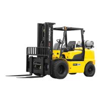
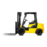
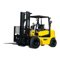
Identification and illustration of the forklift's major components.

2. SPECIFICATIONS

Detailed specifications including capacity, dimensions, and performance metrics.

3. SPECIFICATION FOR MAJOR COMPONENTS

Specific technical details for major components like engine and pumps.

SECTION 2 REMOVAL & INSTALLATION OF UNIT

Group 1 Structure

Structural overview of the unit before removal or installation.

Group 2 Removal and installation of unit

Step-by-step procedures for removing and installing units.

GROUP 1 STRUCTURE

Detailed breakdown of the structure of the unit with component identification.

SECTION 3 POWER TRAIN SYSTEM

Group 1 Structure and operation

Overview of the power train system's structure and operational principles.

Group 2 Inspection and troubleshooting

Guidance on inspecting and troubleshooting power train system issues.

Group 3 Disassembly and assembly

Procedures for disassembling and assembling power train components.

SECTION 4 BRAKE SYSTEM

Group 1 Structure and function

Explanation of the brake system's structure and how it functions.

Group 2 Operational checks and troubleshooting

Procedures for checking brake system operation and troubleshooting common problems.

Group 3 Tests and adjustments

Procedures for testing and adjusting the brake system.

SECTION 5 STEERING SYSTEM

Group 1 Structure and function

Overview of the steering system's structure and operational principles.

Group 2 Operational checks and troubleshooting

Guidance on checking steering system operation and troubleshooting.

Group 3 Disassembly and assembly

Procedures for disassembling and assembling steering system components.

SECTION 6 HYDRAULIC SYSTEM

Group 1 Structure and function

Explanation of the hydraulic system's structure and operational functions.

Group 2 Operational checks and troubleshooting

Procedures for checking hydraulic system operation and troubleshooting issues.

Group 3 Disassembly and assembly

Steps for disassembling and assembling hydraulic system components.

SECTION 7 ELECTRICAL SYSTEM

Group 1 Component location

Identification and location of electrical components on the equipment.

Group 2 Electrical circuit

Diagrams illustrating the electrical circuits of the equipment.

Group 3 Component specification

Technical specifications for individual electrical components.

Group 4 Connector destination

Mapping of connectors to their destinations and part numbers.

Group 5 Troubleshooting

Common electrical problems and their solutions.

SECTION 8 MAST

Group 1 Structure

Detailed structural components of the mast assembly.

Group 2 Operational Checks and Troubleshooting

Procedures for checking mast operation and troubleshooting issues.

Group 3 Adjustment

Methods for adjusting mast components for proper function.

Group 4 Removal and Installation

Instructions for removing and installing mast components.

Related product manuals