
A
Audrey AndrewsAug 1, 2025
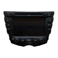
What to do if Hyundai LAN2100EHDM power does not turn on?
- DDanielle PerezAug 1, 2025
If your Hyundai Car Navigation system isn't powering on, there might be several reasons: * Ensure the ignition switch is turned to the ON position or set to ACC. * Verify the unit itself is powered on by pressing the power button on the control panel. * If the system is experiencing operational issues due to noise or other factors, try turning it off and then on again. * As a last resort, you can reset the unit by pressing the RESET hole with a sharp object.