For further information and details, consult our Concept Drawings – which provide detail on specific single
and multiple boiler applications “Piping”, “Wiring” and “Settings”. (available at www.ibcboiler.com or from
your IBC Representative).
Note
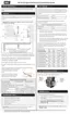
The piping drawings in this manual are simple schematic guides to a successful installation.
There are many necessary components not shown, and details such as thermal traps are left
out so the drawings have greater clarity. We require that our boilers be installed by licensed
and experienced trades people who are familiar with the applicable local and national codes.
System design is to be completed by an experienced hydronic designer or Engineer. It is
necessary to carefully read and follow these installation instructions along with the application
drawing that fits your system.
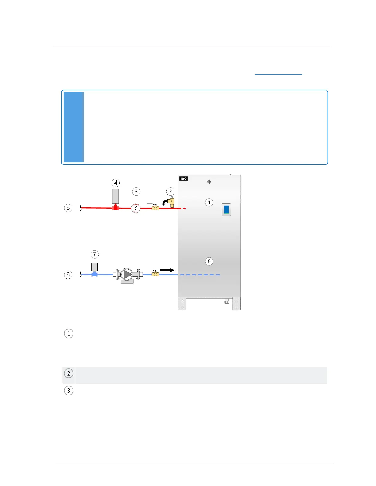
Low water cut-off (LWCO): the IBC EX series comes factory-equipped with an internally mounted
Certified Low Water Cut-Off. Sometimes an external device is required by local jurisdiction. These
devices have specific installation requirements not illustrated here. Consult the IBC factory or the
LWCO manufacturer for proper application of these devices.
Pressure relief valve (ships with boiler): no isolation valve permitted between boiler and relief valve.
Tridicator / external pressure and temperature gauge (ships with boiler).
 Loading...