7.2 Electronic components
This section details the method for troubleshooting the non-standard electronic components on the boiler.
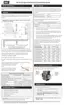
7.2.1 Temperature sensors
The resistance of the temperature sensors varies inversely with temperature. To test, measure the
temperature of the sensed environment and compare with the value derived from the measurement of the
resistance (obtained by connecting a good quality test meter capable of measuring up to 5,000 kΩ
(5,000,000Ω) at the controller end of the sensor lead).
To obtain a resistance reading, remove power to the boiler. For the supply water, return water, and vent
temperature sensors, remove the wire leads by disconnecting their respective Molex connectors. Place
multi-meter probes into the sensor’s female Molex connector socket. Do not apply voltage to the sensor
as damage may result.
The supply water and vent temperature sensors each contain two separate circuits. Test each pair. Both
circuits must deliver accurate (although not necessarily identical) readings. Note that failures may occur
only within certain temperature ranges.
Temp. °F/°C
Resist.
Ω – Ohm
Temp. °F/°C
Resist.
Ω – Ohm
0 / -18 85,362 100 / 38 5,828
5 / -15 72,918 105 / 41 5,210
10 / -12 62,465 110 / 43 4,665
15 / -9 53,658 115 / 46 4,184
20 / -7 42,218 120 / 49 3,760
25 / -4 39,913 125 / 52 3,383
30 / -1 34,558 130 / 54 3,050
35 / 2 29,996 135 / 57 2,754
40 / 4 26,099 140 / 60 2,490
45 / 7 22,763 145 / 63 2,255
50 / 10 19,900 150 / 66 2,045
55 / 13 17,436 155 / 68 1,857
60 / 16 15,311 160 / 71 1,689
65 / 18 13,474 165 / 74 1,538
 Loading...