INSTALLATION AND OPERATION INSTRUCTIONS
1-20
SFC COMBI BOILERS SFC-99, SFC-125
1.6 WATER PIPING - SPACE HEATING
1.6.1 General Piping Considerations
The SFC series units include a factory installed, integral heating pump. The
pump is designed to provide adequate ow through the unit and near unit piping.
Primary/secondary piping or the use of a buffer tank / hydraulic separator is
recommended for maximum exibility in multi zone/load applications. Piping
loads in parallel is only acceptable in systems where the minimum ow rate is
guaranteed to be higher than the minimum for the unit and where the unit’s pump
is adequate to provide the required ow rate and pump head for the system.
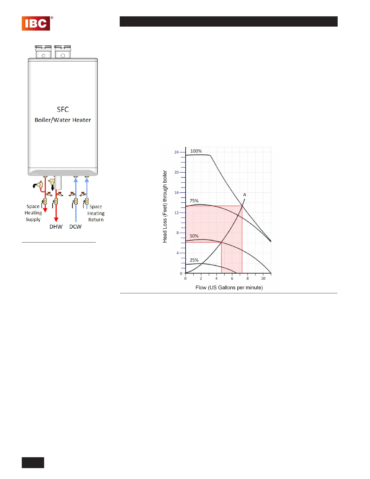
Table 5: Boiler pressure drop - Pump runs between 50% to 100% capacity to establish
pressure difference across boiler circuit
A=boiler pressure drop
The SFC series modulating units are designed for use within a closed loop,
forced circulation, low pressure system. A 30 PSI pressure relief valve (3/4” NPT)
is supplied.
Figure 20: Overview of piping
connections