1-33
INSTALLATION
SFC COMBI BOILERS SFC-99, SFC-125
1.8 GAS PIPING
The unit must have an inlet gas pressure of at least 4.0" w.c. for natural gas and
propane. For either fuel, the inlet pressure shall be no greater than 14.0" w.c.
Conrm this pressure range is available with your local gas supplier.
The inlet gas connection of the unit’s gas valve is 1/2" NPT (male).
Adequate gas supply piping must be provided with no smaller than 1/2" Iron Pipe
Size (e.g. Iron Pipe Size (IPS) and a 1" w.c. pressure drop used, in accordance
with the following chart:
MODEL 1/2" IPS 3/4" IPS 1" IPS
SFC Series (Natural Gas) 20' 70' 200'
SFC Series (Propane) 50' 200' 600'
Table 8: Maximum Pipe Length (ft) – SFC series
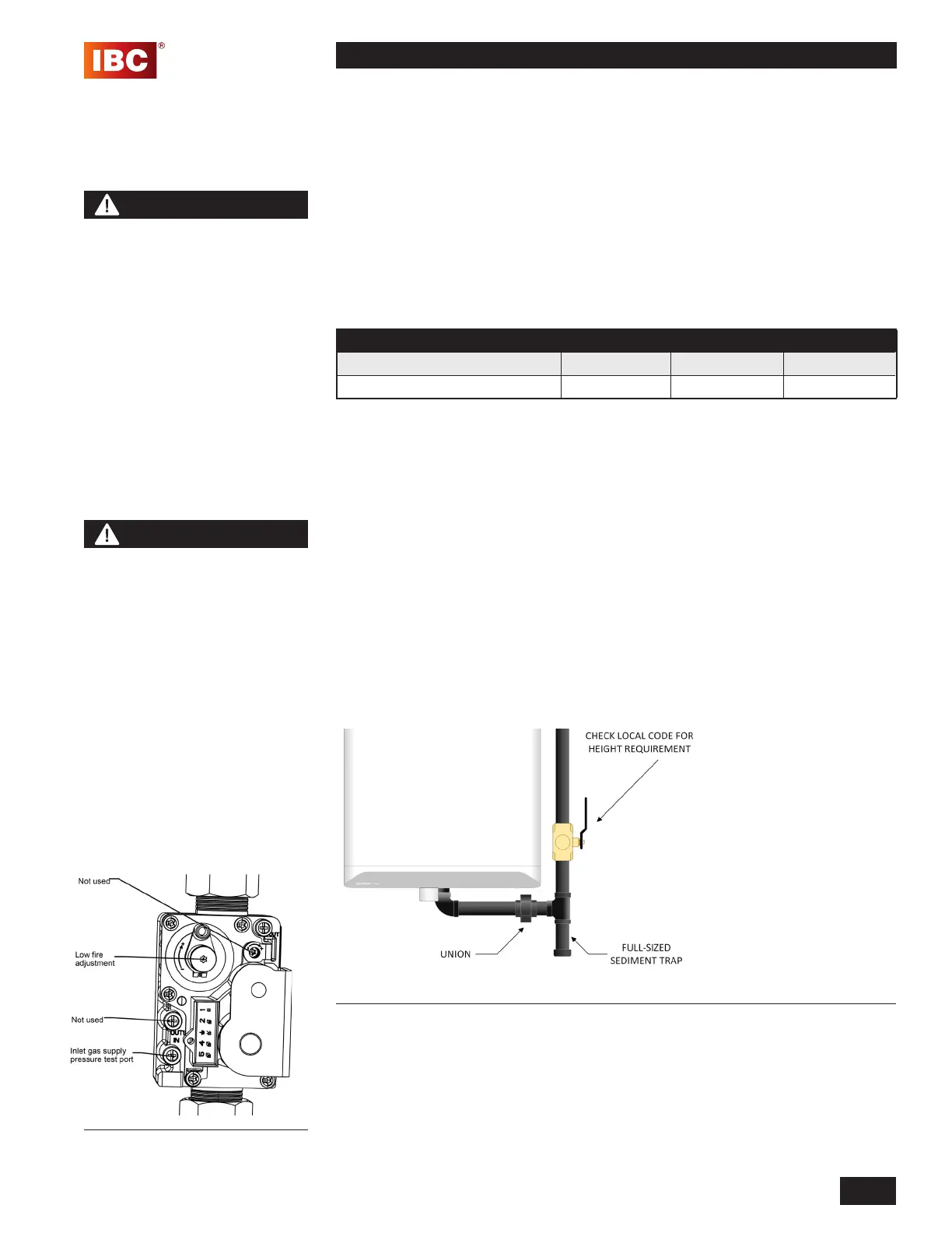
Gas piping must have a sediment trap ahead of the unit’s gas valve (see Figure
33). A manual shutoff valve must be located outside the unit, in accordance with
local codes/standards. All threaded joints in gas piping should be made with an
approved piping compound resistant to the action of natural gas/propane. Use
proper hangers to support gas supply piping as per applicable codes.
The unit must be isolated from the gas supply piping system by closing,
disconnecting and capping its individual manual shutoff valve during any
pressure testing of the gas supply piping system at test pressures equal to or
greater than 1/2 psi (3.5 kPa). Dissipate test pressure prior to reconnecting.
The gas valve is provided with pressure taps to measure gas pressure upstream
(supply pressure) and downstream (manifold pressure) of the gas valve (see
Figure 32). Note that manifold pressure varies slightly in accordance with ring
rates with the modulating series units, but will always be close to 0" w.c.
Figure 33: Gas Piping
WARNING
This appliance can burn
either natural gas or propane.
Refer to section 3.3 for further
instruction. If converting
an appliance from one fuel
to another, you must order
a conversion kit prior to
the conversion. Install the
conversion kit according
to the detailed instructions
supplied with the kit. Failure
to perform the required fuel
conversion correctly can
result in serious injury or
death.
NOTE
It is essential to check gas
supply pressure to each
unit with a manometer or
other high-quality precision
measuring device. Pressure
should be monitored before
ring the unit, when the
regulator is in a “lock-up”
condition and during operation,
throughout the unit’s full
modulation range.
Pay special attention to retrot
situations where existing
regulators may have an over-
sized orice and/or worn seats,
causing pressure “creep” and
high lock up pressures.
Figure 32: Gas Valve