Exhaust venting installation
Exhaust venting must slope down towards the boiler with a pitch of at least ¼" per foot (PPs
vent: follow PPs manufacturer requirements for slope), so condensate runs back towards the
trap. Support should be provided for intake and vent piping where it passes through unheated
spaces or underground, with appropriate pipe insulation to prevent freezing of condensates.
Certain installations of the SLmodels can employ 2"vent options. We caution installers when
using horizontal runs of 2"pipe. Air friction from the fast moving exhaust during long burner
runs at high-fire in a 2"pipe can overcome gravity on ¼"per foot vent slope, leaving a pool of
condensate at the next upturned elbow. Pooling can impair the achievement of full high-fire
rating plate performance.
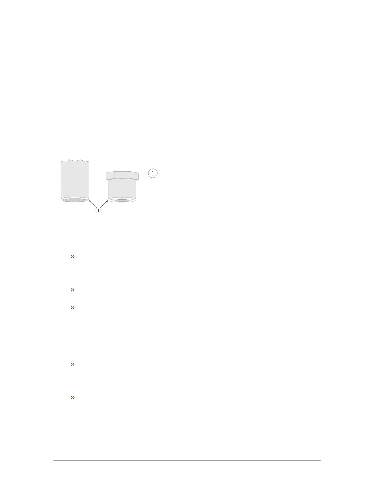
Ensure pipe and fittings are beveled for trouble-free
insertion through exhaust and intake pipe gaskets. Wet
gaskets and pipe before insertion.
Figure 15 Pipe and fitting beveling
Exhaust piping is inserted directly into the left connector on the top of the boiler, then runs
horizontally or vertically to the outdoors. Screen material can be placed at the outlet as
appropriate for the environment (e.g., insects, dust).
Check that material meets local codes including fire stopping requirements. Some local
jurisdictions require a minimum initial length of pipe be exposed or accessible for
inspection. Pipe clearances - no IBC requirements; follow local codes. All piping must
be liquid and pressure tight.
Ensure all venting components are clear of burrs/debris prior to assembly. Clear plastic
debris left in the combustion air piping to avoid intake into the fan.
Secure joints using appropriate solvent cement to bond the respective pipe material
(Canada: CPVC cement approved under ULC-S636, in accordance with its
manufacturer instructions; USA: PVC (ASTM D2564), or PVC/ABS (D2235) - Use
transition glue anywhere that PVC and CPVC are joined. Follow the cement
manufacturer’s instructions closely when joining various components. For PPs,
connections shall be secured using approved retainer clips supplied by the respective
PPs manufacturer.
Check that vent connections are liquid and pressure tight. Prior to firing the boiler, and
before any of the venting run is concealed by the building construction, test the exhaust
joints under fan pressure with the vent blocked, using a soap and water solution. The
installer must fill the condensate trap prior to testing.
Coat all joints with an approved leak test solution just as you would joints in a gas line,
and make sure that there are no leaks. We suggest attaching a tag on the vent line near
the condensate drain tee with the type of test, the date and the installer’s name.

 Loading...


