INSTALLATION AND OPERATION INSTRUCTIONS
1-8
VFC 15-150 - VFC 45-225 MODULATING GAS BOILERS
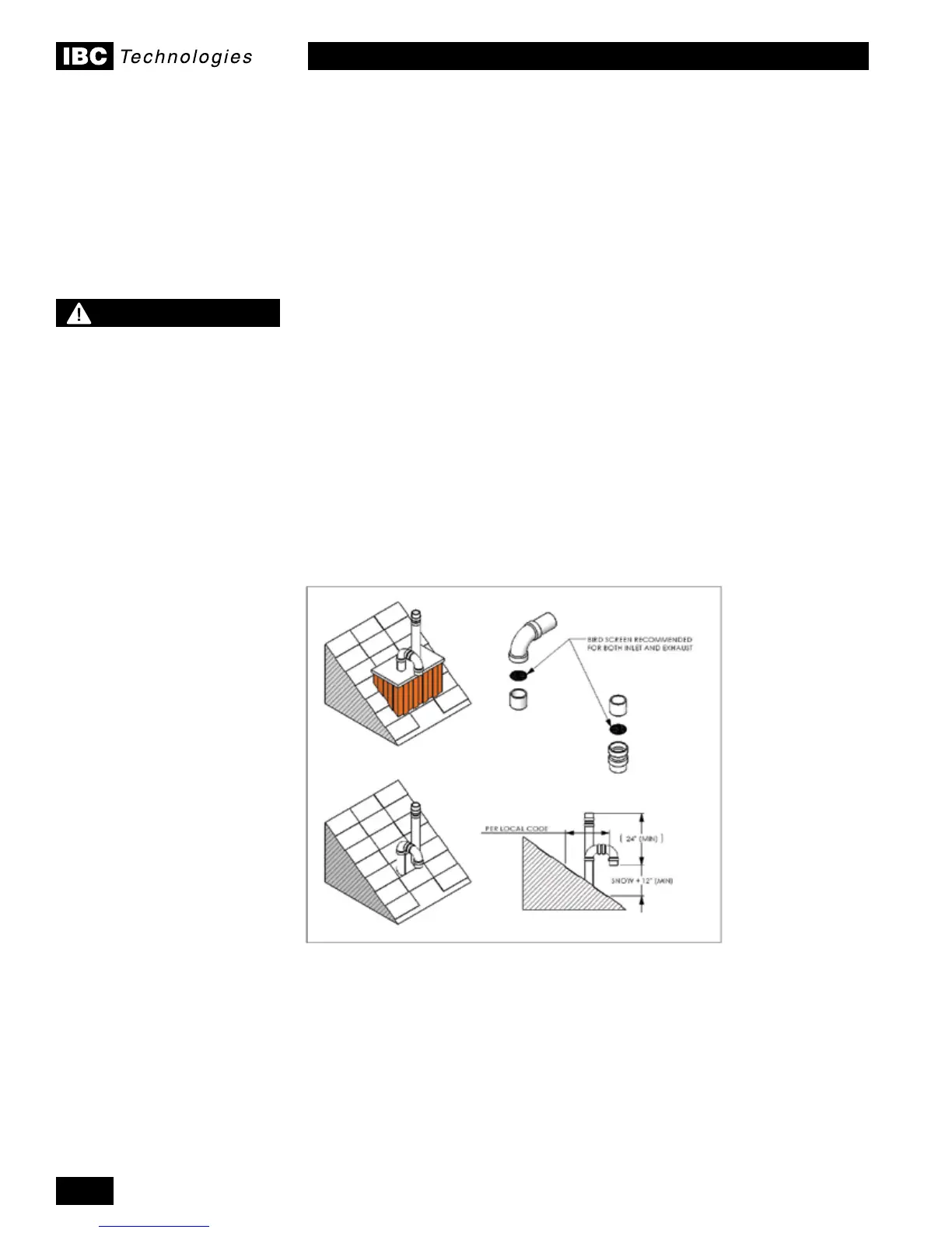
Figure 3: Rooftop vent terminal congurations
1.4.6 Sidewall Vent Termination
Sidewall direct vent applications shall be vented as follows:
• Both the inlet and exhaust terminations should normally be located on the
same plane (side) of the building.
• The exhaust outlet is to be placed so as to reach 24" minimum above the
down-turned intake - to avoid exhaust re-ingestion.
• The elevation of both pipes can be raised in “periscope style” after passing
throughthewall,thenconguredasinFigure 4, to gain required clearance.
1.4.5 Rooftop Vent Termination
Rooftop vents must terminate as follows:
• The exhaust pipe can terminate in an open vertical orientation without
concernaboutraininltration;thiswilldrainawaythroughaproperly
conguredcondensatetrap.
• If used, the intake air pipe is not typically drained, so it must be terminated with
a down-turned elbow (see Figure 3). The intake pipe does not need to penetrate
the roof at the same elevation as the exhaust (as shown); lower down roof is OK.
• To promote the projection of exhaust away from the building and from the
intake pipe, reduction of 3" pipe to 2" is permitted for a maximum lineal travel
of3'(e.g.thenal3')including2x90°elbowsoneachside.
• Optionalbirdscreenmaybeplacedinaterminationtting.Leaveunglued,
and hold in place with a short nipple. This permits easy access for cleaning.
• For roof top venting of multiple boiler sets, group all intake terminals together
for a common penetration through a custom cap. Alternatively, place in the
closestproximityachievableusingcommonlyavailablepipeashing.Similarly
group the exhaust pipes and place the 2 separate groups of pipes at least 3'
apart (the closest intake and exhaust pipes shall be 36" - or more - apart).
Use the same 24" (minimum) vertical separation for all termination options.
For alternate group terminations, contact the IBC Factory for written guidance.
• DO NOT exhaust vent into a common venting system.
WARNING
Condensate can cause
corrosion of metal roong
components and other
roong materials. Check
with the builder or roong
contractor to ensure that
materials will be resistant to
acidic condensate. pH levels
can be as low as 3.0

 Loading...


