INSTALLATION AND OPERATION INSTRUCTIONS
2-8
VFC 15-150 - VFC 45-225 MODULATING GAS BOILERS
In an “open loop” reset system, a room or zone thermostat is used to send a call
for heat over a 24VAC lead; this opens the respective zone valve, and signals the
boilertoreusingonwardleadstotheboiler’sdrycontacts(useoneofthepairs
marked “Therm 1, 2 or 3” on the orange connector terminal located on the right
edge of the controller). Gang such leads in parallel from multiple zone valves for
single connection to the boiler. Note that typical room thermostats simply provide
a call for heat, they do not control the circulating water temperature from the
boiler in an open loop reset system. Adjustment of a room thermostat from 23°C
to30°Cwillmakenofurtherdifferencetothedeliveredtemperatureiftheoor
slab has stabilized at the boiler temperature served up by the reset curve.
Where Outdoor Reset is applied without the indoor sensor feedback option, some
manual adjustment may be required to achieve the desired comfort level. Fine
adjustment can be made at the keypad using the Indoor Setpoint Temperature
variable, located as Line 1 in the User screen. To increase heat (e.g. from 72°F to
73°) - move the Indoor value upward (warmer) from the level otherwise chosen.
This shifts the position of the reset curve, will amend the boiler water temperature
by a similar amount. Do not adjust the Design Indoor Temp. value - a movement
upward in concert with Line 1 adjustment will have the effect of neutralizing the
intended effect.
Anoptionalindoortemperaturefeedbackroutinecanbeactivated(witheld
installation of an indoor sensor, connected to the contacts located on the
controller) to automate adjustment of the Outdoor Reset routine.
The key inputs on initial set up are (1) Design Outdoor Temperature – the coldest
expected weather typically experienced at the installation site; (2) the Design
Supply Temperature – the desired boiler operating level to occur at that coldest
day; and (3) the Design Indoor Temp. - this is the value that anchors the reset
curve. The Indoor Set Point Temp. variable is the primary means for the user to
“bias” the outdoor reset routine to add or reduce heat.
If outdoor reset is selected and there is no signal received from the sensor,
the controller assigns a provisional 0°C value and will adopt the appropriate
temperature target from the relevant reset curve.
See Section 2.7 Set Up & Load Denition for activation procedure.
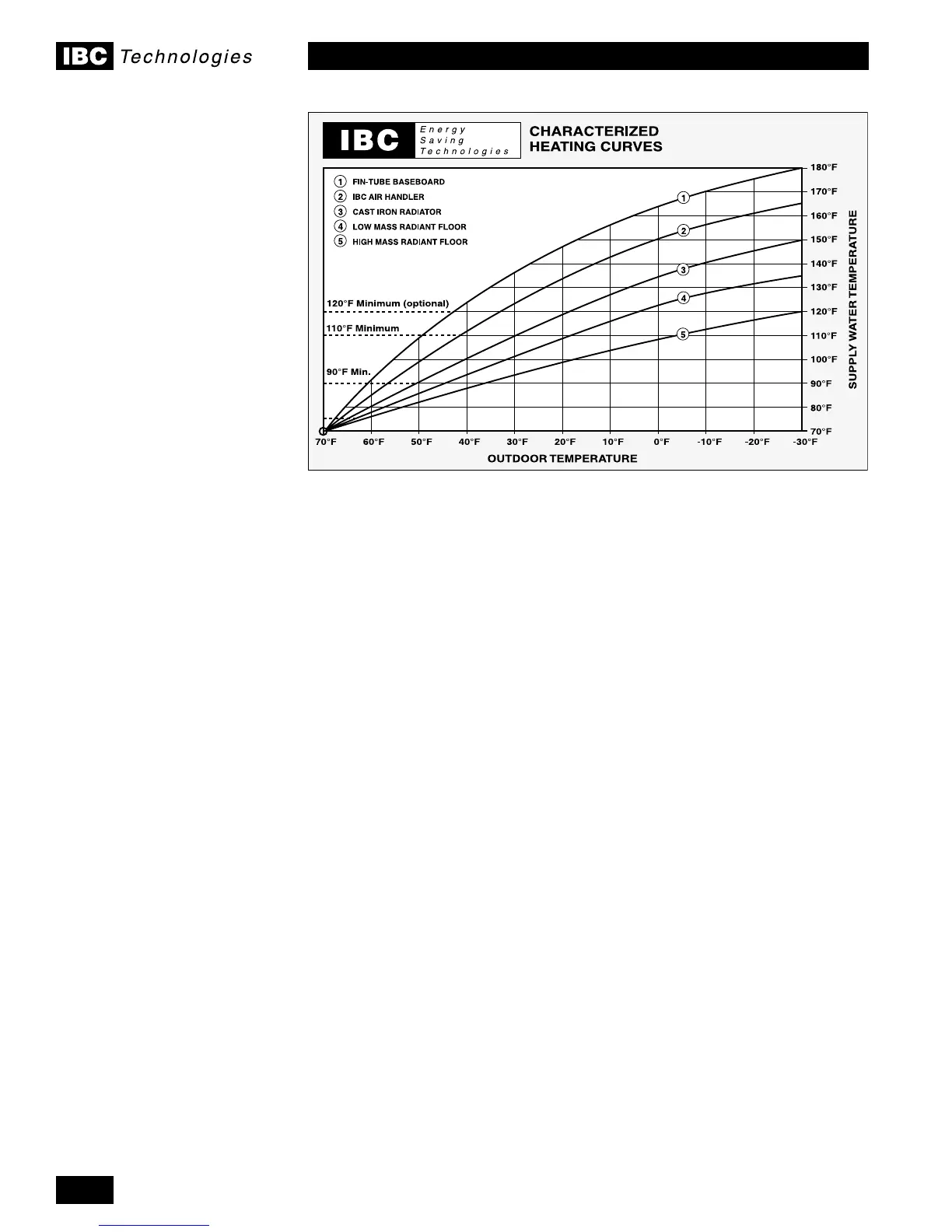
Figure 30: Outdoor reset curves

 Loading...


