1-23
INSTALLATION
VFC 15-150 - VFC 45-225 MODULATING GAS BOILERS
shallbecarriedoutaftertheretrot,withlterclearingafterthe1stday,1stweek,
monthandannuallythereafter.Careistobetakentoavoiduseofferrousttings
and pumps on PB tube systems.
1.6.2 Installation Rules
NOTE: The Boiler Trim element – common to each of the following systems
-includesthepressurerelief,ll,expansiontankandairbleedelements.The
primary pump can be located on either the Supply or Return piping sections.
Features of the preferred Primary / Secondary piping system:
1. Goodcirculatingwaterowthroughtheboilerirrespectiveofloadorradiation
system head
2. AllowsexibleΔT°controlinsecondaryloops
3. Adds to the system’s thermal buffering, to assist in handling small loads and
temperature transition.
Thispipingcongurationrequiresanextrapump.TheVFCmodulatingseries
boilers’ controller hosts wiring terminals and integral relays to simplify installation
and operation of this preferred layout, offsetting such costs.
For optimal performance, place pumps on the supply side of secondary loops
to facilitate air evacuation. Use pumps with internal check valves to avoid ghost
owsandthermalsiphoning.
The primary loop temperature may need to transition from a 180°F domestic water
heatingloadtoa100°Fradiantoorrequirement.Thesecondarypumpswillswap
off/on simultaneously, provided the pre-set maximum allowable temperature of the
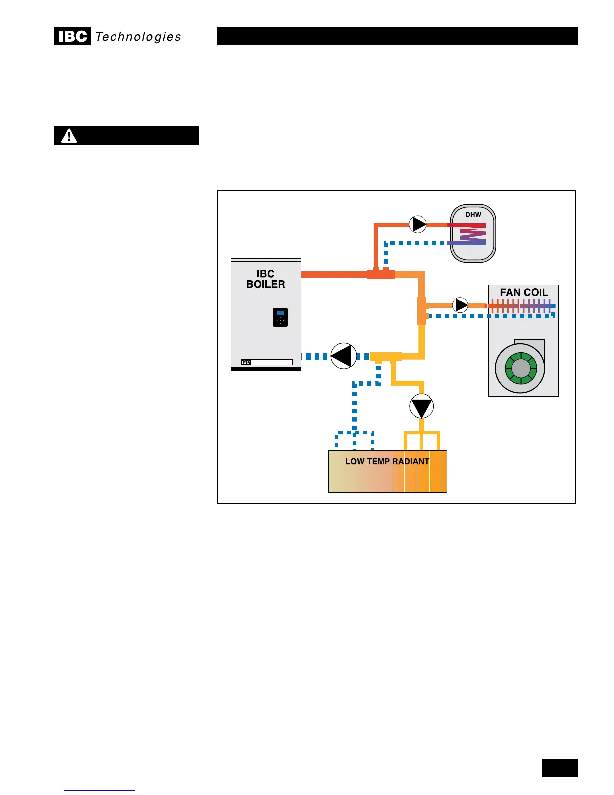
Figure 26: Basic Primary/Secondary, 3 load piping concept
NOTE
This piping drawings in this
manual are simple schematic
guides to a successful
installation. There are many
necessary components not
shown, and details such as
thermal traps are left out so
the drawings have greater
clarity. We require that
our boilers be installed by
licensed and experienced
trades people who are familiar
with the applicable local
and national codes. System
design is to be completed
by an experienced hydronic
designer or Engineer. It is
necessary to carefully read
and follow these installation
instructions along with the
application drawing that ts
your system.
 Loading...


