INSTALLATION AND OPERATION INSTRUCTIONS
1-24
VFC 15-150 - VFC 45-225 MODULATING GAS BOILERS
new load is not exceeded. In the case of the typical maximum limit for a radiant
oor(mostwouldenter140°F);theoorpumpwouldremainoff,theboilershut
down, leaving primary circulation on until the primary loop temperature drops into
theacceptablerangefortheoor.Temperaturesensingisdoneusingthermistors
at the boiler supply and return – no further sensors need to be installed.
The use of the multi-temperature modulating system is optimized when the need
to shutdown the boiler is reduced or eliminated during the transitional period.
System design enhancements: (a) keep a relatively low thermal mass in the
primary loop, and (b) incorporate a 3-way mixing valve on the “cool” load piping.
If the installation involves small loads, as in typical zoned baseboard heating
applications, use of a buffer tank is recommended. To aid in temperature
transition from hot to cool loads, a 3-way mixing valve can be placed at the
entrancetothecoolload(thiswillalsoprovideoorprotection).Thiswillpermit
immediatecirculationofmixedowintothecoolloop.Seeseparatepublication
Application Notes for more detail (available at www.ibcboiler.com or from your
IBC Representative).
Alwaysensurethatloadssensitivetohightemperatures(e.g.radiantoor)
are protected using appropriate means such as a manual mixing valve, or an
aquastat (set to130°F, for example) wired to the boiler’s auxiliary interlocks.
Compared with the Primary/Secondary approach, the above design saves one
pump.Lostisthesimplicityofconstantheadandowattheboiler,withreduced
exibilityinthehandlingoflargetemperaturedifferentials.Wiring:looptheyellow
& white “Primary Pump” pair up to connect to the lowest pair of contacts on
the green Pump/Valve terminal block. Then connect the two load pumps to the
chosen Load 1-2-3 contacts on the same green terminal block.
Check valves or thermal traps should be used to isolate both the supply and
returnpipingforeachload-toavoidthermalsiphoningandreverseow.
Toensureadequatewaterowthroughtheboilerunderhigh-head/singlezonespace
heating conditions, a pressure activated bypass or other means of bypass must be
usedonanyloadwheretheowratemightdropbelowminimumrequirements(4gpm
for the 15-150, 8 gpm for the 45-225).
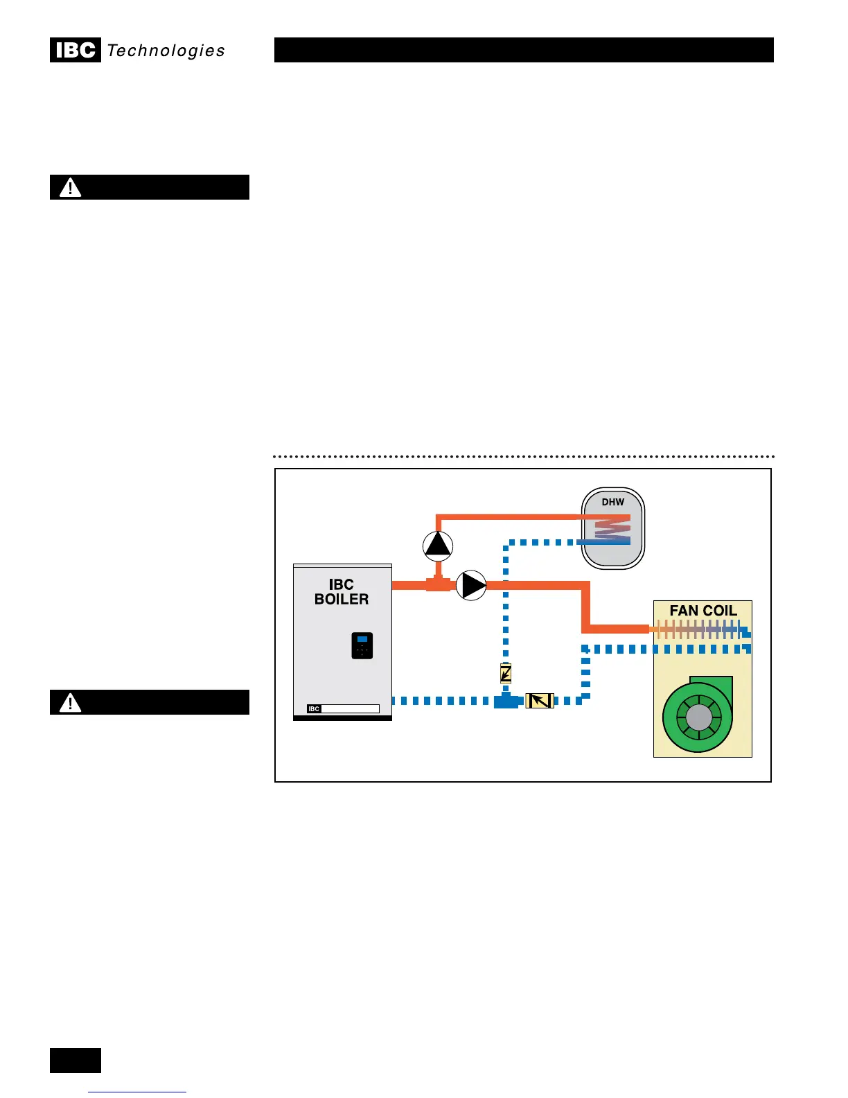
Figure 27: Two pump, two load - parallel piping concept
NOTE
When using the sequential
load feature of the IBC boiler,
attention must be paid to
the operation of system
components in order to
ensure they are compatible.
Many air handlers (fan
coils) for instance have a
thermostat connection that
will energize an internal relay
to operate the air handler
circulator and its fan on
a call for heat. This may
result in operation of these
components when other
loads are running at a higher
priority, resulting in cold air
blowing, or robbing heat from
another load.
Some wiring alteration may
be required to divorce both
of these functions from
thermostat control in favour
of more effective control from
the IBC boiler.
NOTE
For information and details
regarding Multiple Boiler
application, consult our
Technical Notes - Multiple
Boiler Systems. These notes
provide necessary detail on
specic single and multiple
boiler applications “Piping”,
“Wiring” and “Settings”.
(available at www.ibcboiler.
com or from your IBC
Representative).
 Loading...


