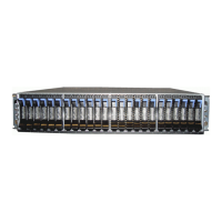
5. Use the initialization GUI to enter the requested information, such as the management IP address and service IP addresses. (You need
to set the IP address, subnet mask, and DNS server only when you do not want to use DHCP.) For more information, see Management
and service address worksheet on page 11.
Adding the control enclosure to an existing system
If the system was already set up on another control enclosure, do not install it again on this control enclosure. Instead, use the management
GUI to add the control enclosure to the system.
1. Connect the node canisters to the storage area network or to a 25 Gbps (or faster) Ethernet.
2. Configure the zoning on the SAN switches. The correct zoning provides a way for the FC ports to connect to each other.
If the new node canisters communicate with other node canisters by using RDMA over Ethernet, use the service assistant tool or the
satask chnodeip command to set the node IP of each node that will be in the system.
3. In the management GUI, select Monitoring > System. On the System - Overview page, select Add Enclosure.
When a new enclosure is cabled correctly to the system, this action automatically displays on the System - Overview page. If this action
does not appear, ensure that the new enclosure is cabled correctly. You can also add a new enclosure by selecting Add Enclosure from
the System Actions menu.
4. Complete the instructions in the Add Enclosure wizard until the control enclosure is added to the system.
5. If only two control enclosures are in the system, you must set up a quorum disk or application outside of the system. If the two control
enclosures lose communication with each other, the quorum disk prevents both I/O groups from going offline.
Installation worksheets
Worksheets can help you plan and install the system. You can also use the worksheets to track important information if you must remove
and reinstall parts during the installation process. Complete the worksheets for each control enclosure that you are installing.
Drive configuration worksheet
The control enclosure supports up to 24 drives, which are installed in drive slots on the front of the enclosure. The drives must be installed
according to specific guidelines. Use the worksheet to configure the drives on your system.
Most NVMe drives and Storage Class Memory (SCM) drives can be installed in any drive slot. The highest capacity drive must be installed
in the lowest available drive slot. However, if 375 GB (02PX477) or 750 GB (02PX482) Optane SCM drives are used, the drives must be
installed in specific slots.
• Optane SCM drives can be installed only in drives slots 21 - 24. Install the highest capacity drive in the highest available drive slot.
• Other NVMe or SCM drives can be installed in slots 1 - 24. The highest capacity drive must be installed in the lowest available drive slot.
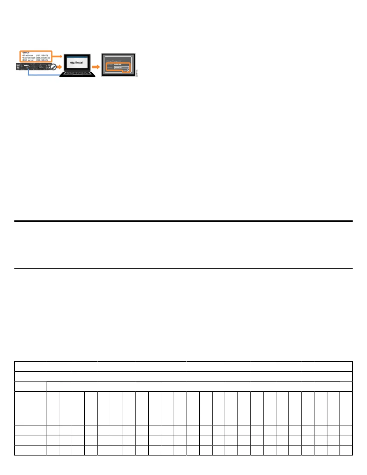
Drive installation worksheet
Use the following table to record information about the drives in the control enclosure. For each drive slot, specify the type and capacity of
the drive or whether a drive blank is installed. For a list of supported drives, see Supported drives on page 11.
Control Enclosure S/N:
Content Drive Slots
Type
NVMe
Other SCM
Optane SCM
Capacity
Drive Blank
Slot 1 2 3 4 5 6 7 8 9 10 11 12 13 14 15 16 17 18 19 20 21 22 23 24
Table 1: Drive installation worksheet

 Loading...