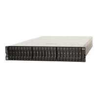
Supported drives
The following table lists the supported drives for the system. For more information about replaceable units, see IBM Knowledge Center.
FRU Part Number Description
01YM585 800 GB 2.5" NVMe Flash drive
01YM586 1.92 TB 2.5" NVMe Flash drive
01YM587 3.84 TB 2.5" NVMe Flash drive
01YM588 7.68 TB 2.5" NVMe Flash drive
01YM589 15.36 TB 2.5" NVMe Flash drive
02PX477 375 GB 2.5" NVMe Optane SCM drive
02PX478 750 GB 2.5" NVMe Optane SCM drive
02PX482 800 GB 2.5" NVMe SCM drive
02PX483 1.6 TB 2.5" NVMe SCM drive
02YC416 4.8 terabytes usable (TBu) / 21.99 terabytes effective (TBe) NVMe IBM FlashCore Modules (FCM) 2.0
02YC417 9.6 TBu / 21.99 TBe 2.5" NVMe FCM 2.0
02YC418 19.2 TBu / 43.98 TBe 2.5" NVMe FCM 2.0
02YC419 38.4 TBu / 87.96 TBe 2.5" NVMe FCM 2.0
Table 2: Control enclosure drives
Management and service address worksheet
Use the following table to record the management address and service addresses for each control enclosure. The primary system address
is bound to Ethernet port 1. The secondary system address, if specified, is bound to Ethernet port 2. Both IPv4 and IPv6 addresses can be
used. Specify the type of installation and the serial number (S/N) of the control enclosure.
• If you are installing a new system installation, designate new, unused IP addresses.
• If you are adding an I/O group (control enclosure) to an existing system, use the management address of the existing system.
Control Enclosure S/N: Are you adding this control enclosure to an existing system?
❐
Yes
❐
No
Address Type IP Address Network Mask Default Gateway
Primary system address (required)
Optional secondary system address (optional)
Node canister 1 service address (required)
Node canister 2 service address (required)
Table 3: Magement IP address and service IP address worksheet
Network cable worksheet
Use the cable-connection tables to record the location and type of cable connections for each control enclosure in the system.
Ethernet cable standards
The control enclosure supports Ethernet connection by using onboard ports and ports on networking adapters. The following table
summarizes the Ethernet cable standards for each connection.
Ethernet port type Cable type Minimum standard Connector
1 Gbps Ethernet technician port TP Cat 5e RJ45
Table 4: Ethernet cable standards

 Loading...