Connecting SAS cables
This task applies if you are installing one or more SAS-attached expansion enclosures. Each control enclosure in the system can manage
two chains of 2U and 5U expansion enclosures. The system supports an intermix of 2U and 5U expansion enclosures with a total chain
weight of 10 in each of two SAS chains.
Important: In the control enclosure, node canister 1 is on top and node canister 2 is on the bottom. Because the node canisters are
inverted, the location of the ports and the numbering of the ports are oriented differently on each node canister. It is important to
remember this orientation when you are installing adapters and cables.
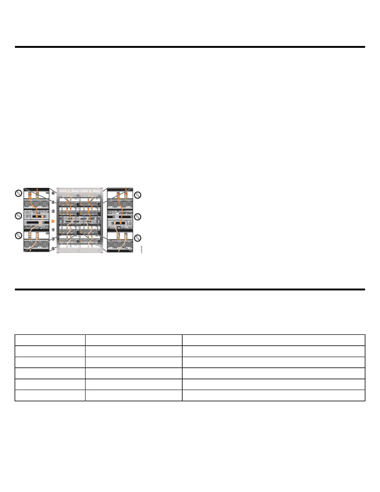
1. Using the supplied SAS cables, connect the control enclosure to the first expansion enclosure.
a. Connect SAS port 1 of the top node canister (node 1) in the control enclosure to SAS port 1 of the left expansion canister in the first
expansion enclosure.
b. Connect SAS port 1 of the bottom node canister (node 2) in the control enclosure to SAS port 1 of the right expansion canister in the
first expansion enclosure
2. To add a second expansion enclosure chain to the control enclosure, complete the following steps.
a. Connect SAS port 3 of the top node canister in the control enclosure to SAS port 1 of the left expansion canister in the second
expansion enclosure.
b. Connect SAS port 3 of the bottom node canister in the control enclosure to SAS port 1 of the right expansion canister in the second
expansion enclosure.
For more information about 2U and 5U expansion enclosures, see IBM Knowledge Center (https://ibm.biz/BdqxdY).
Connect networking cables
To provide connectivity for the system, you must connect cables to the appropriate ports on the control enclosure.
Four 10 Gbps Ethernet ports on each node canister provide system management connections and iSCSI host connectivity. The onboard
10 Gbps Ethernet ports use RJ-45 connections. The 10 Gbps ports operate at 1 Gbps when connected to a 1 Gbps switch. A separate
technician port provides access to initialization and service assistant functions.
Onboard Ethernet Port Speed Function
1 10 Gbps Management IP, Service IP, Host I/O
2 10 Gbps Secondary Management IP, Host I/O
3 10 Gbps Host I/O
4 10 Gbps Host I/O
T 1 Gbps Technician Port - DHCP/DNS for direct attach service management.

 Loading...