attaches the hinge to the rack from under the rack top hat. Use a torque screwdriver to tighten the
screws to 2.5 Nm ± 0.2 Nm (22.1 inch lbs ± 1.8 inch lbs).
22. When the heat exchanger is latched, make sure that there is a tight t between the heat exchanger
and the rack frame. Loosen or tighten the latch adjustment screw as required.
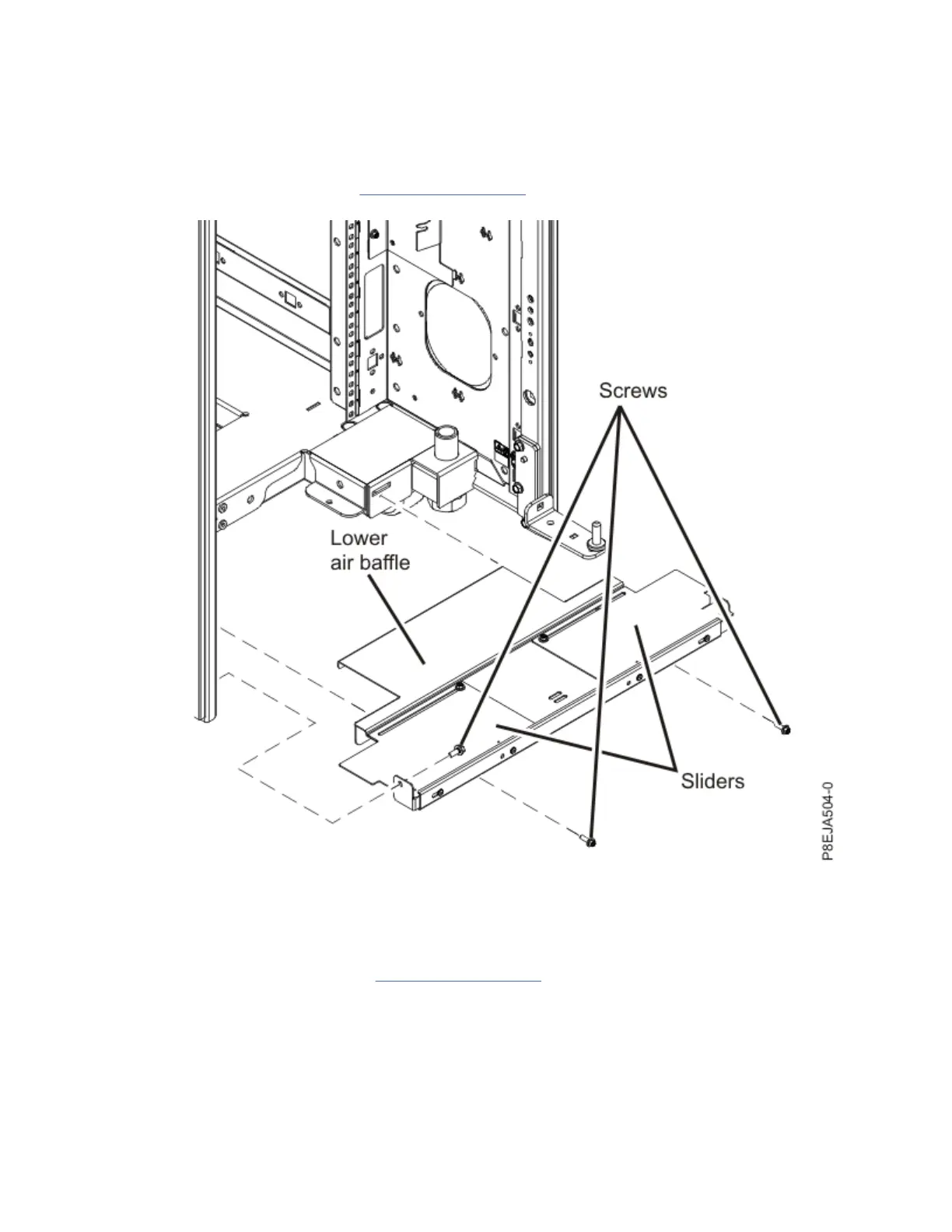
23. Install the lower air baffle in the rear of the rack. Secure the air baffle to the rack with two M5 and
two M6 screws, as shown in Figure 108 on page 151. Use a torque screwdriver to tighten the screws
to 2.5 Nm ± 0.2 Nm (22.1 inch lbs ± 1.8 inch lbs).
Figure 108. Aligning the bottom hole with the hinge pin
24. Install the hose guide peg by using one M5 screw. Use a torque screwdriver to tighten the screw to
2.5 Nm ± 0.2 Nm (22.1 inch lbs ± 1.8 inch lbs).
25. Route the hoses under the rack. Ensure that one hose is on each side of the hose guide peg.
26. Couple the hoses, as shown in Figure 109 on page 152.
Racks and rack features
151
 Loading...