j. Align the blank ller panel (A) on the outside of the rack flanges, as shown in Figure 44 on page
61.
k. Attach the ller panel to the rack flanges and then to the long mounting bracket with one M6
screw (B) per bracket. Use the screws that were provided with the rack mounting kit.
l. Proceed with step “15” on page 62.
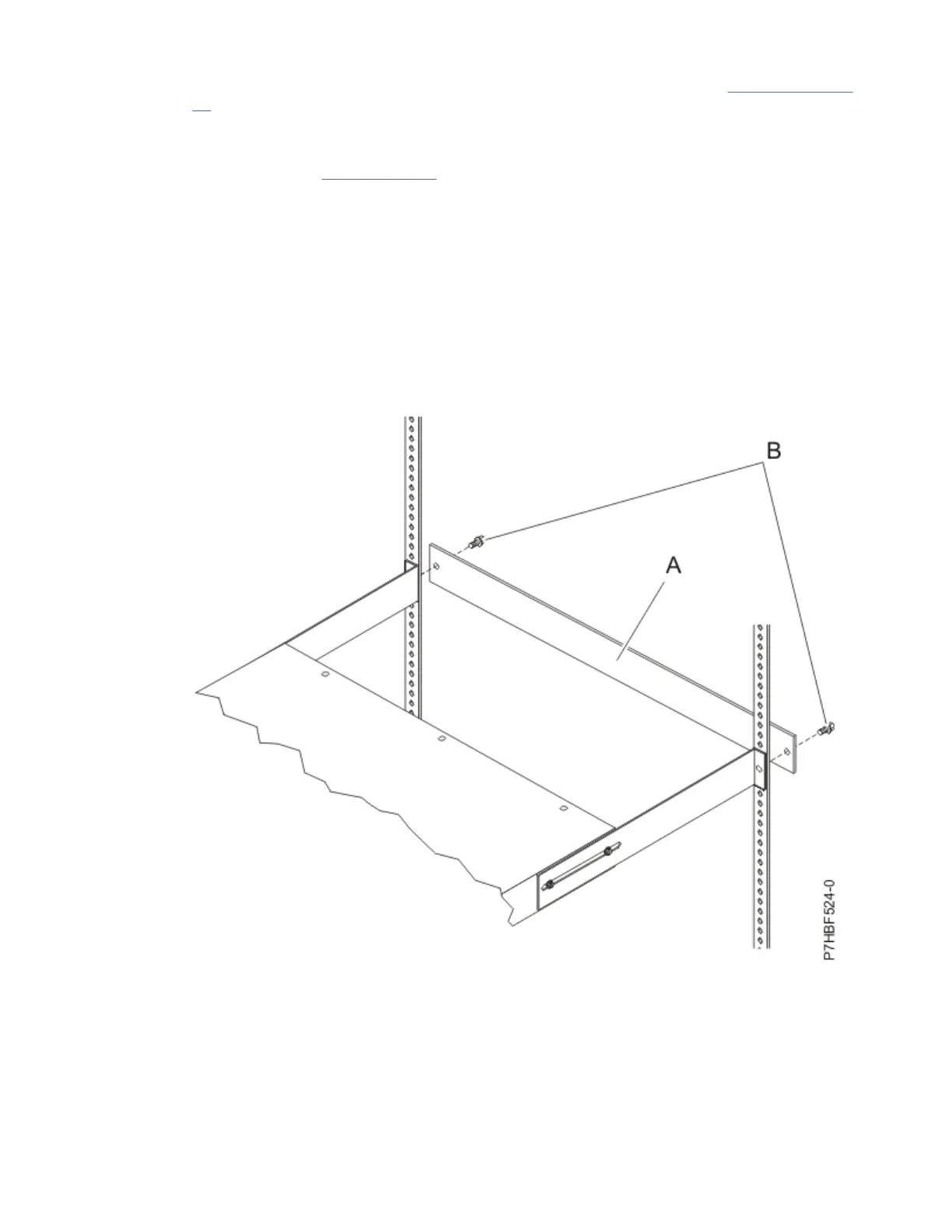
14. Secure the long mounting brackets and the blank ller panel (A) to the rack cabinet by completing
the following steps:
a. Adjust the long mounting brackets to t the depth of the rack cabinet.
b. Tighten the M3 pan-head screws that secure the long mounting brackets to the PDU, PDU+,
Intelligent Switched PDU, or Intelligent Switched PDU+ model.
c. Make sure that the long mounting brackets are aligned with the inside of the rack flanges.
d. Align the blank ller panel (A) on the outside of the rack flanges.
e. Attach the ller panel to the rack flanges and then to the long mounting bracket with one M6
screw (B) per bracket. Use screws that were provided with the rack mounting kit.
Figure 45. Attaching the brackets and ller panel to the rack
15. If the PDU, PDU+, Intelligent Switched PDU, or Intelligent Switched PDU+ model was provided with a
detached power cord, connect the power cord now.
Align the connector on the power cord (A) that was provided with the PDU, PDU+, Intelligent
Switched PDU, or Intelligent Switched PDU+ model with the connector on the front of the unit (A),
turning as necessary for key alignment. Then, turn the twist-lock (B) on the connector clockwise until
it locks into place.
62
Power Systems: Racks and rack features
 Loading...