4 Fan release latch
5 Fan fault indicator
6 Expansion canister
7 SAS ports and indicators
8 Expansion canister indicators
9 Power cable connector for PSU 1
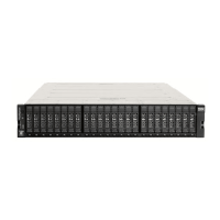
Support rails
Figure 18 on page 39 shows the support rails for the expansion enclosure. The support rails are
packaged separately from the expansion enclosure.
Figure 18. Support rails
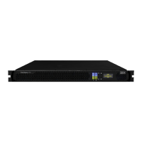
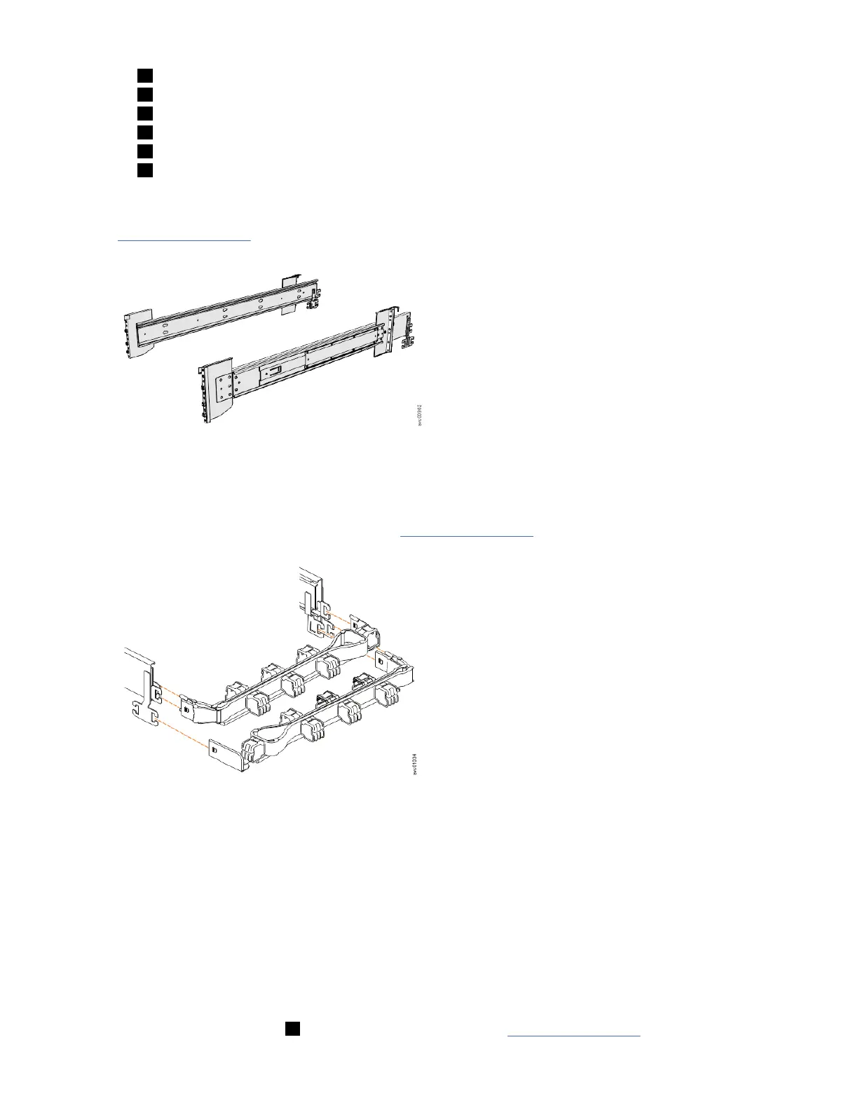
Cable management arm
The cable management arm (CMA), which consists of an upper and lower assembly, are packaged
separately from the expansion enclosure. As Figure 19 on page 39 shows, each CMA assembly is
attached to the rear end of the support rails.
Figure 19. CMA assemblies
Removing the top cover
To complete some service tasks, you might need to remove the top cover from a 5U expansion enclosure.
Before you begin
Important: You can remove the cover without powering off the expansion enclosure. However, to
maintain operating temperature, replace the cover within 15 minutes of its removal. When the cover is
removed, the reduction in airflow through the enclosure might cause the enclosure or its components to
shut down to protect from overheating.
Procedure
1. Slide the release latch ( 1 ) in the direction that is shown in Figure 20 on page 40.
Chapter 4. Installing the system hardware
39