the bus number value, BBBB, in word 7 of the SRC, see “Breaking down the SRC” on page 63
(located in the Bus PIP Overview topic) for help in determining the bus number. Search for the bus
number in HSM or the System Configuration Listing to determine which frame or I/O tower contains the
failing component. Record the frame or tower type.
2. The failing component is the FRU containing the logical card slot that is controlled by the multi-adapter
bridge. Identify the system model, tower, expansion unit, or machine type that is indicated by the
location in the SAL, or by using the bus number, BBBB. Using the information provided in the table
below, exchange the FRU that is indicated.
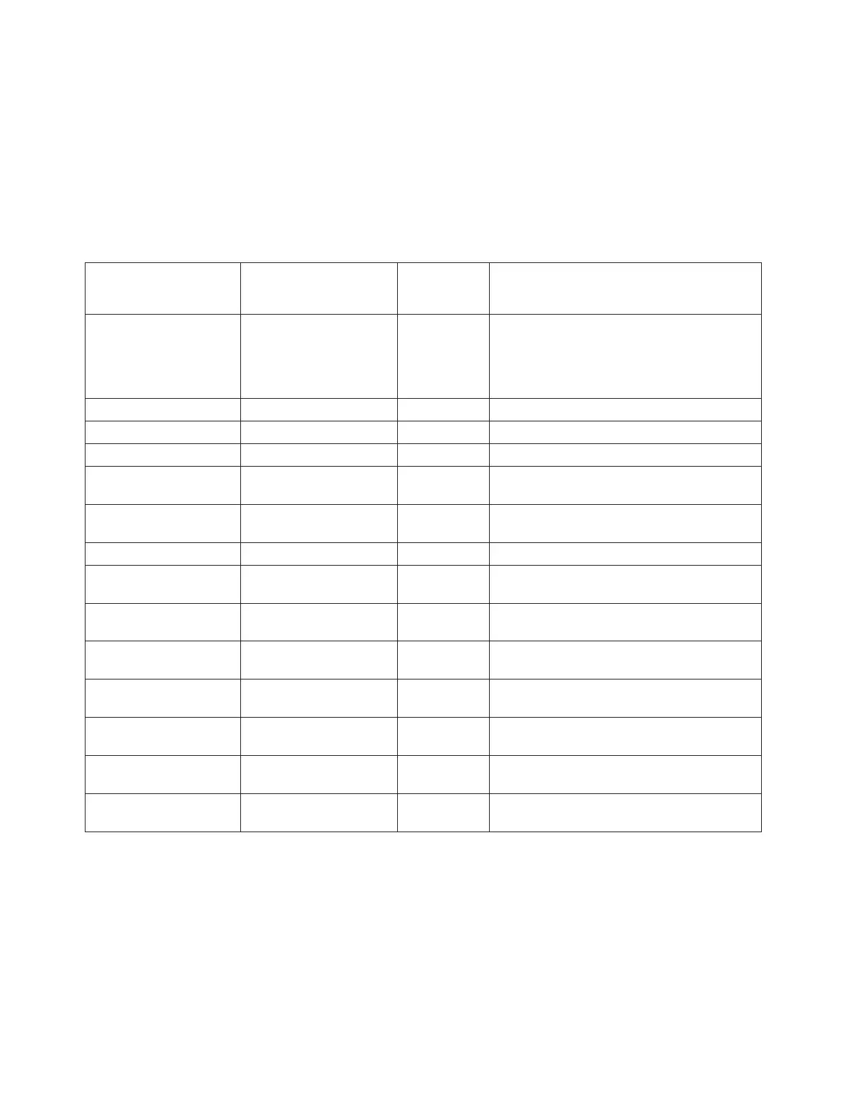
Table 1. Failing component service information for symbolic FRU MASBUS
System model, tower,
expansion unit, or
machine type
Name of FRU to
exchange
FRU position Link to failing component service
information (CCIN, location diagram, and
removal and replace procedures)
Model 270 Record the
processor feature code
(characters 5 through 8 of
function 20 on the control
panel)
System unit backplane MB1 Use the Model 270 diagrams and tables by
processor feature code and follow the
locations diagram link or the FRU positions
and failing components link for the processor
feature code.
Models 800 and 810 System unit backplane MB1 See Locations — Models 800 and 810
Model 820 System unit backplane MB1 See Locations — Model 820
Model 825 System unit backplane MB1 See Locations — Model 825
Models 830 and SB2
base I/O tower (FC 9074)
Tower card CB1 See Locations — Models 830, SB2 system
unit with FC 9074 base I/O tower
Models 840 and SB3
base I/O tower (FC 9079)
Tower card CB1 See Locations for FC 9079 base I/O tower
(on Models 840, SB3 system unit)
Models 870 and 890 Tower card CB1 See Locations — Models 870 and 890
FC 5074 expansion I/O
tower
Tower card CB1 See Locations — FC 5074 I/O tower
FC 5075 expansion I/O
tower
Tower card CB1 See Locations — FC 5075 I/O tower
FC 5078/0578 expansion
I/O unit
Tower card CB1 See Locations — FC 5078, 0578 expansion
I/O unit
FC 5079 (1.8m expansion
tower)
Tower card CB1 See Locations — FC 5079 Expansion I/O
Tower
FC 5088, FC 0588
Expansion I/O Unit
Tower card CB1 See Locations — FC 5088, FC 0588
Expansion I/O Unit
FC 5095, FC 0595
Expansion I/O Tower
Tower card CB1 See Locations — FC 5095, FC 0595
Expansion I/O Tower
External xSeries Server Integrated xSeries
Adapter Card
Follow the
HSL cables.
See Locations — Integrated xSeries Adapter
Card (IXA)
This ends the procedure.
MDAPWR
For use by authorized service providers.
The Motor Drive Assembly (MDA) may be the failing item.
1. Use the table below to find the part number you need.
2. Refer to the Models 870 and 890 - MDA (air mover) controller remove and replace procedure.
3. See Type, model, and part number list for the part number.
Note: Before replacing any FRU’s verify that all cables are seated correctly.
400 iSeries: iSeries Server 270, 800, 810, 820, 825, 830, 840, 870, 890, SB2, and SB3 Hardware Problem Analysis and
Isolation

 Loading...


