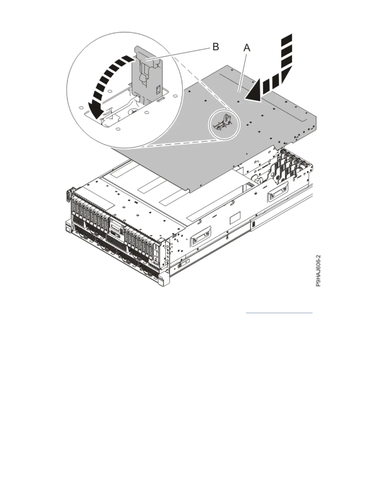
Figure 130. Installing the service access cover
For a stand-alone system, complete the following steps. Refer to Figure 131 on page 136.
a. Slide the cover (B) on to the system unit as shown.
b. Close the latch release (A) by pushing it in the direction shown.
Control panel cables for the 9009-41A, 9009-42A, or 9223-42H
135
 Loading...