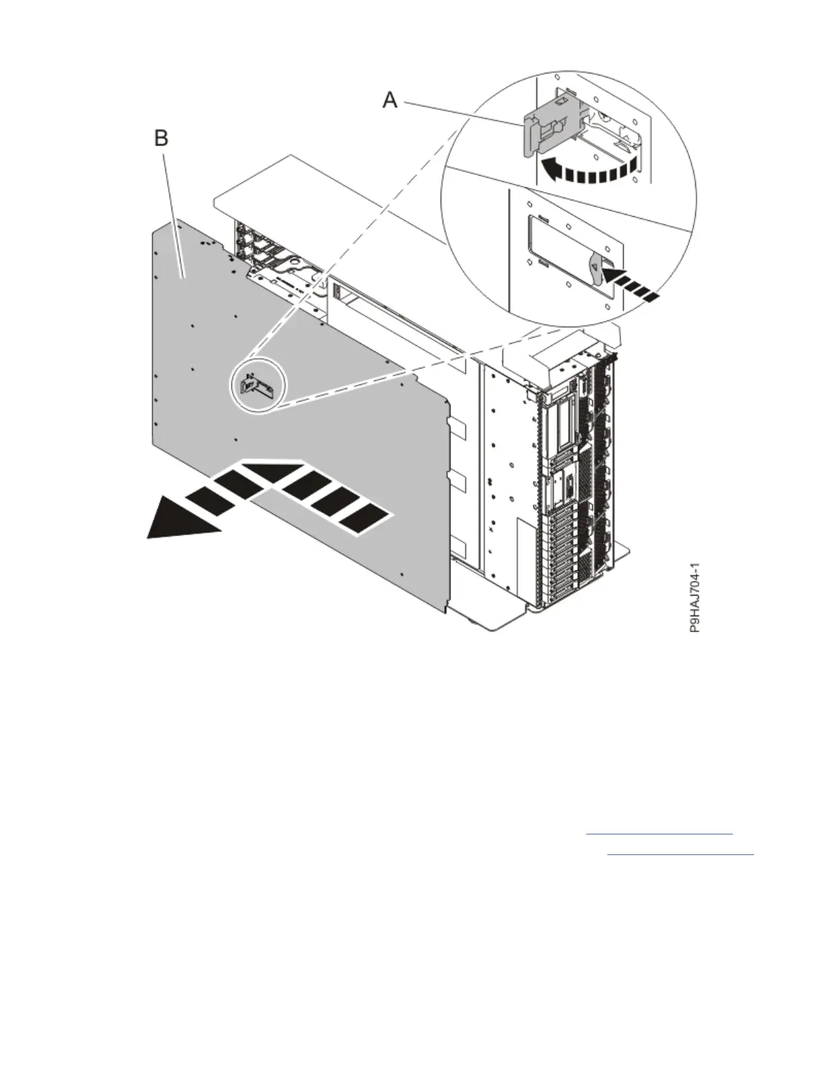
Figure 104. Removing the service access cover
Removing the control panel display cable from the 9009-41A, 9009-42A, or 9223-42H
system
To remove a control panel display cable, complete the steps in this procedure.
Procedure
1. Ensure that you have the electrostatic discharge (ESD) wrist strap on and that the ESD clip is plugged
into a ground jack or connected to an unpainted metal surface. If not, do so now.
2. For a rack-mounted system, lift the air baffle (A) straight up as shown in Figure 105 on page 110
.
For a stand-alone system, remove the air baffle (A) straight out as shown in Figure 106 on page 111.
Place the air baffle upside down on a clean area so that the foam does not collect contaminants.
Control panel cables for the 9009-41A, 9009-42A, or 9223-42H
109
 Loading...