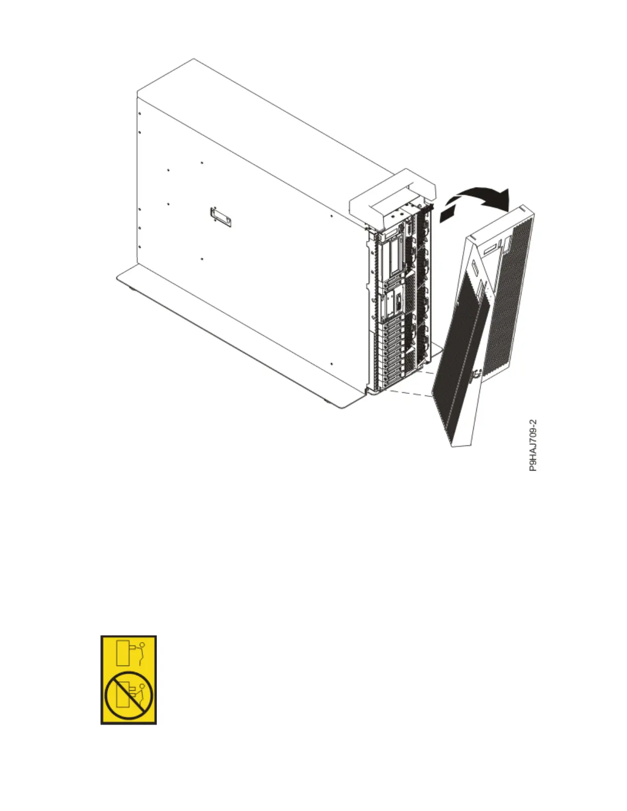
Figure 54. Removing the front cover
7. For a rack-mounted system, open the side latches (A) and pull the latches to slide the system unit fully
into the service position until the slides click and hold the system unit securely. Ensure that the screws
inside the latches are not secured to the rack.
See the following gure.
Remove the hook-and-loop fasteners that secure the cable management arms. Ensure that the cable
management arms can move freely. Ensure that the cables at the rear of the system do not catch or
bind as you pull the system unit into the service position.
Do not pull out or install any drawer or feature if the rack stabilizer brackets are not attached to the
rack. Do not pull out more than one drawer at a time. The rack might become unstable if you pull out
more than one drawer at a time.
58
Power Systems: Power Systems: Control panel
 Loading...