Chapter 2. The POWER7 processor 31
The rest of this section covers multiple topics that can affect application performance,
including the effects of cache geometry, alignment of data, and sensitivity to the scaling of
applications to more cores. Tips are provided for using the various functionalities that are
provided in Power Systems and AIX.
Cache geometry
Cache geometry refers to the specific layout of the caches in the system, including their
location, interconnection, and sizes. These design details change for every processor chip,
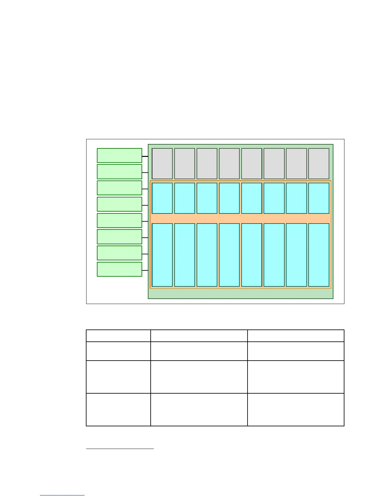
even within the Power Architecture. Figure 2-2 shows the layout of a POWER7 chip, including
the processor cores, caches, and local memory. Table 2-6 shows the cache sizes and related
geometry information for POWER7.
Figure 2-2 POWER7 chip and local memory
17
Table 2-6 POWER7 storage hierarchy
18
17
Ibid
Cache POWER7 POWER7+
L1 i-cache:
Capacity/associativity 32 KB, 4-way 32 KB, 4-way
L1 d-cache:
Capacity/associativity
bandwidth
32 KB, 8-way
2 16 B reads or
1 16 B writes per cycle
32 KB, 8-way
2 16 B reads or
1 16 B writes per cycle
L2 cache:
Capacity/associativity
bandwidth
256 KB, 8-way
Private
32 B reads and 16 B writes per cycle
256 KB, 8-way
Private
32 B reads and 16 B writes per cycle
18
Ibid
Processor Chip
L2
256 KB
L2
256 KB
L2
256 KB
L2
256 KB
L2
256 KB
L2
256 KB
L2
256 KB
L2
256 KB
L3
4 MB
L3
4 MB
L3
4 MB
L3
4 MB
L3
4 MB
L3
4 MB
L3
4 MB
L3
4 MB
Core Core Core Core Core Core Core Core
Memory DIMM
Memory DIMM
Memory DIMM
Memory DIMM
Memory DIMM
Memory DIMM
Memory DIMM
Memory DIMM
Cache