v Voltage monitoring
v Fan monitoring
v Temperature monitoring
v Real-time clock (RTC) with battery
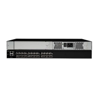
Port side of the switch
The port side (see Figure 1) includes the system status LED, console port, Ethernet
port and LEDs, USB port, and Fibre Channel ports and the corresponding port
status LEDs.
1 System status LED 4 FC ports 0-3 (all
LEDs above)
7 Switch ID pull-out
tab
2 Management
Ethernet port with
LEDs
5 System power LED 8 FC ports 4-7
3 USB port 6 Serial console port
Note: The two LEDs on the serial console port are nonfunctional.
Nonport side of the switch
Figure 2 shows the non-port side of the switch, which contains the power supply
(including the AC power receptacle and AC power switch) and fan assemblies. The
base model configuration with a single assembly is shown.
1 Power supply
filler panel
4 On/off power
switch
7 Handle
2 Power
supply/fan
assembly #1
5 Power plug
receptacle
4
2
3
1
6
7
8
5
b245001
Figure 1. Port side view
1 2 3
7
6
4 5
b245002
5
Figure 2. Non-port side of the switch
Chapter 1. Introducing the SAN24B-5 3
 Loading...