management GUI. The fix procedures minimize the risk of losing data or access
to data; the procedures also manage the system's use of the drive.
About this task
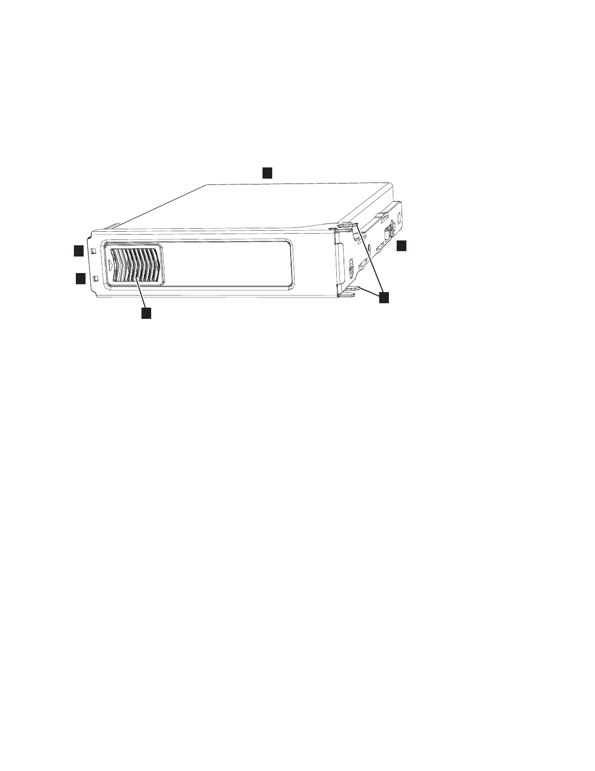
The 2077-92F expansion enclosure supports 92 drives. Figure 59 shows an example
of a drive assembly.
▌1▐ Disk drive
▌2▐ Online indicator
▌3▐ Fault indicator
▌4▐ Release latch
▌5▐ Drive latch toes
▌6▐ Drive carrier
Procedure
1. Read all the available safety information.
2. Carefully slide the expansion enclosure out of the rack, as described in
“Removing an expansion enclosure from a rack: 2077-92F” on page 95.
3. Remove the cover, as described in “Removing the top cover: 2077-92F” on
page 48.
4. Locate the empty drive slot to receive the new drive or that contains the
faulty drive that you want to replace.
Note: When a drive is faulty, the amber fault indicator is lit (▌3▐ in Figure 59).
Do not replace a drive unless the drive fault indicator is on or you are
instructed to do so by a fix procedure.
A label on the enclosure cover (Figure 60 on page 74) shows the drive
locations in the enclosure. The drive slots are numbered 1-14 from left to right
and A-G from the back to the front of the enclosure.
Figure 59. Drive assembly
Chapter 2. Installing the system hardware 73
 Loading...


