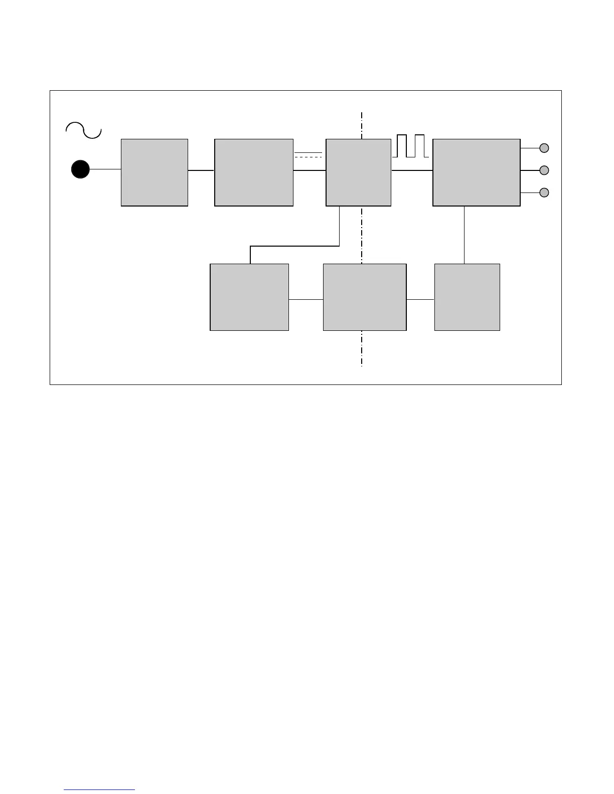
POWER BOADR
1. EMI components.
This part contains of EMI components to comply with global marketing EMI standards like FCC, VCCI CISPR,
the circuit included a line-filter, across line capacitor and of course the primary protection fuse.
2. Input rectifier and filter.
This part function is for transfer the input AC voltage to a DC voltage through a bridge rectifier and a bulk
capacitor.
3. Energy Transfer.
This part function is transfer the primary energy to secondary through a power transformer.
4. Output rectifier and filter.
This part function is to make a pulse width modulation control and to provide the driver signal to power switch,
to adjust the duty cycle during different AC input and output loading condition to achive the dc output stablize,
and also the over power protection is also monitor by this part.
5. Photo-Coupler isolation.
This part function is to feed back the dc output changing status through a photo transistor to primary controller
to achive the stablized dc output voltage.
6. Signal collection.
This part function is to collect the any change from the dc output and feed back to the primary through photo
transistor
DESCRIPTION OF BLOCK DIAGRAM