Patent No. 424,953
7313 William Barry Blvd., North Syracuse, NY 13212
(Toll Free) 800-365-5525 (Phone) 315-233-5266 (Fax) 315-233-5276
www.icmcontrols.com
ONE-YEAR LIMITED WARRANTY
The Seller warrants its products against defects in material or workmanship for a period of one (1)
year from the date of manufacture. The liability of the Seller is limited, at its option, to repair, replace
or issue a non-case credit for the purchase prices of the goods which are provided to be defective.
The warranty and remedies set forth herein do not apply to any goods or parts thereof which have
been subjected to misuse including any use or application in violation of the Seller’s instructions,
neglect, tampering, improper storage, incorrect installation or servicing not performed by the Seller.
In order to permit the Seller to properly administer the warranty, the Buyer shall: 1) Notify the Seller
promptly of any claim, submitting date code information or any other pertinent data as requested by
the Seller. 2) Permit the Seller to inspect and test the product claimed to be defective. Items claimed
to be defective and are determined by Seller to be non-defective are subject to a $30.00 per hour
inspection fee. This warranty constitutes the Seller’s sole liability hereunder and is in lieu of any other
warranty expressed, implied or statutory. Unless otherwise stated in writing, Seller makes no warranty
that the goods depicted or described herein are t for any particular purpose.
LIAF083-2
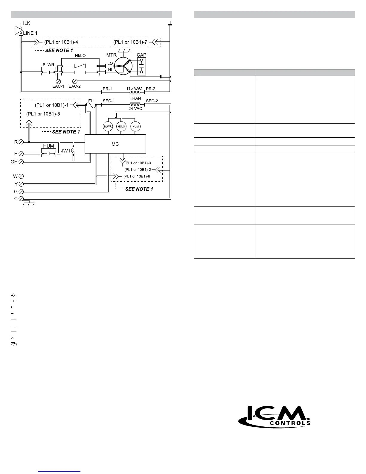
Wiring Diagram
LEGEND:
CAP Run Capacitor
TRAN Transformer
JW1 Jumper Wire
MTR Motor, Blower
MC Microcontroller
FU Fuse (ATO 3-amp)
HI/LO Blower Motor Speed
Change Relay (DPST)
HUM Humidier Relay (SPST-NO)
BLWR Blower Motor Relay (SPST-NO)
ILK Switch, Blower Door Interlock (SPST-NO)
Plug Receptacle
Junction
Unmarked Terminal
Terminal PCB
Factory Wiring (115 VAC)
Factory Wiring (24 VAC)
Conductor on PCB
Screw Connector
Equipment Ground
Note 1: PL1 and 10B1 indicates 7-PIN edge connector terminations that connect to
control center. Refer to unit wiring diagram for specic unit wiring from control
center edge connector.
Troubleshooting
Symptom Remedy
Continuous low speed blower • Check for open fuse
• Check for open limit
• Check for 24 VAC at R and C terminals
• Check if JW1 is cut
• Check edge connector slot 1 and slot 5; with no
power applied and the edge connector removed,
there should be continuity between edge
connector slot 1 and slot 5
Blower speed not correct • Check if R18 is cut
• Check wiring of LO and HI terminals
No fan for heating or cooling • Check for 24 VAC at SEC1 and SEC2
No fan delays • Verify test pins are not shorted
No fan on heat call • Check for 24 VAC at R and C terminals
• Check for 24 VAC at SEC1 and SEC2
• Check edge connector slot 3 and slot 6; with no
power applied and the edge connector removed,
there should be continuity between edge
connector slot 3 and slot 6
• No input from W
• Bad edge connector
• Bad wire in edge connector or harness
Status LED blinking • Status LED blinks when 24 VAC is applied to
SEC1 and SEC2; there are no fault ash codes
for this control
Intermittent fan operation • Check for constant 24 VAC at R and C terminals
• Bypass thermostat and test operation of fan
control; with no power applied, remove wires
to thermostat; use a jumper wire to initiate a
call for heat/cool blower; if operation is correct,
thermostat or thermostat wire is faulty
WARNING!
:
High voltage! Troubleshooting this fan control board involves
working with high voltage which can result in personal injury, death
and/or property damage.
CAUTION!
:
Always disconnect power by removing a fuse or opening a circuit
breaker before doing continuity checks. Verify power is not present
before troubleshooting.
CAUTION!
:
Troubleshooting tasks should only be performed by those trained to
install or service HVAC equipment.
 Loading...