4
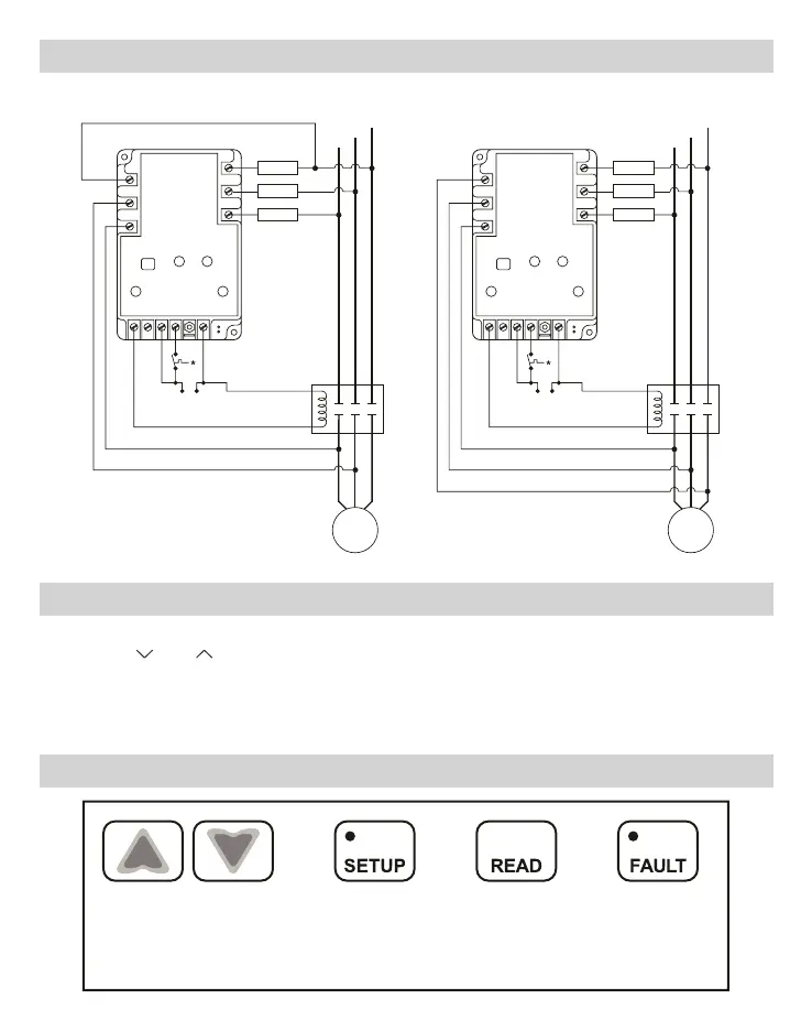
Wiring Diagrams
* Thermostat pressure switch, etc.
Fuse
Fuse
Fuse
LINE
3
LINE
1
LINE
2
LOAD
1
LOAD
2
LOAD
3
Control
Voltage
L01
L02
L03
L0AD
LI1
LI3
LI2
* Thermostat pressure switch, etc.
Fuse
Fuse
Fuse
LINE
3
LINE
1
LINE
2
LOAD
1
LOAD
2
LOAD
3
Control
Voltage
L01
L02
L03
L0AD
LI1
LI3
LI2
3-Pole Contactor2-Pole Contactor
Setting the Parameters
1. Press the green SETUP button to enter Setup mode. Setup LED will light.
2. Use the and arrows to change user parameters.
3. Scroll through setup by pressing and releasing the SETUP button.
4. When the last parameter has been set, the phase average will be displayed and
the Setup LED will automatically turn OFF.
Button Functions
Press to read
faults. Hold for 5
seconds to clear
faults and reset
memory.
Press arrows to scroll
through and select user
parameter settings in
Setup mode. HOLD
down for fast edit.
Press to enter
Setup mode
and select user
parameters.
Hold for
voltage display
aèb, bèc, aèc
(simultaneously).
 Loading...