B - 3 - 2
ATTENUATOR
R16–R24
SWR DETECTOR
CIRCUIT
INPUT
C7
C8
D8
D7
C12
C15
C16
R33
R34
R151
IC19
R27
D11
D12
C17
Q4
C19
C20
TO Q5
TO IC15
BUFFER
AMP
OUTPUT
(TO RL2)
(FROM RL1)
ATTENUATOR
R16–R24
SWR DETECTOR
CIRCUIT
INPUT
C6
From R193
L2
L3
D6
R14
D81
IC19
D5
R15
BUFFER
AMP
Q4, Q5
TO IC15
OUTPUT
(TO RL2)
(FROM RL1)
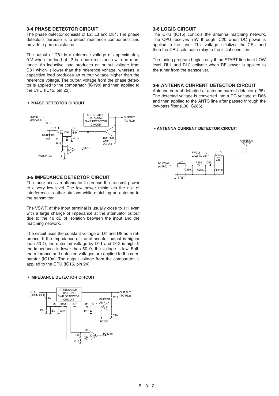
• PHASE DETECTOR CIRCUIT
• IMPEDANCE DETECTOR CIRCUIT
C285
L36
C286
R259
R258
L35
L37
TO W501
(ANTC)
L302 TO L317
FROM
ANTENNA
D86
• ANTENNA CURRENT DETECTOR CIRCUIT
3-4 PHASE DETECTOR CIRCUIT
The phase detector consists of L2, L3 and D81. The phase
detector’s purpose is to detect reactance components and
provide a pure resistance.
The output of D81 is a reference voltage of approximately
0 V when the load of L3 is a pure resistance with no reac-
tance. An inductive load produces an output voltage from
D81 which is lower than the reference voltage, whereas, a
capacitive load produces an output voltage higher than the
reference voltage. The output voltage from the phase detec-
tor is applied to the comparator (IC19b) and then applied to
the CPU (IC15, pin 23).
3-5 IMPEDANCE DETECTOR CIRCUIT
The tuner uses an attenuator to reduce the transmit power
to a very low level. The low power minimizes the risk of
interference to other stations while matching an antenna to
the transmitter.
The VSWR at the input terminal is usually close to 1:1 even
with a large change of impedance at the attenuator output
due to the 16 dB of isolation between the input and the
matching network.
The circuit uses the constant voltage at D7 and D8 as a ref-
erence. If the impedance of the attenuator output is higher
than 50 Ω, the detected voltage by D11 and D12 is high. If
the impedance is lower than 50 Ω, the voltage is low. Both
the reference and detected voltages are applied to the com-
parator (IC19a). The output voltage from the comparator is
applied to the CPU (IC15, pin 24)
3-6 LOGIC CIRCUIT
The CPU (IC15) controls the antenna matching network.
The CPU receives +5V through IC20 when DC power is
applied to the tuner. This voltage initializes the CPU and
then the CPU sets each relay to the initial condition.
The tuning program begins only if the START line is at LOW
level. RL1 and RL2 activate when RF power is applied to
the tuner from the transceiver.
3-8 ANTENNA CURRENT DETECTOR CIRCUIT
Antenna current detected at antenna current detector (L35).
The detected voltage is converted into a DC voltage at D86
and then applied to the ANTC line after passed through the
low-pass filter (L36, C286).